ES-FA-11AA BANNER ENGINEERING, ES-FA-11AA Datasheet - Page 14
ES-FA-11AA
Manufacturer Part Number
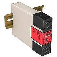
ES-FA-11AA
Description
98H7885
Manufacturer
BANNER ENGINEERING
Datasheet
1.ES-FA-11AA.pdf
(16 pages)
Specifications of ES-FA-11AA
Coil Voltage Vac Nom
24V
Coil Voltage Vdc Nom
24V
Contact Current Max
7A
Contact Voltage Ac Nom
250V
Contact Voltage Dc Nom
250V
No. Of Poles
2
Relay Mounting
DIN Rail
External Height
80mm


14
Category
Output Response Time
Input Requirements
Minimum OFF-State Recov-
ery Time
Indicators
Construction
Mounting
Vibration Resistance
Operating Conditions
Design Standards
Certifications
Banner Engineering Corp. - Minneapolis, MN USA - www.bannerengineering.com
Specification
Mechanical life: > 20,000,000 operations
Electrical life (switching cycles of the output contacts, resistive load): 150,000
cycles @ 1,500 VA; 1,000,000 cycles @ 450 VA; 2,000,000 cycles @ 250 VA;
5,000,000 cycles @ 125 VA
NOTE: Transient suppression is recommended when switching inductive
loads. Install suppressors across load. Never install suppressors across output
contacts (see Warning, Wiring of Arc Suppressors).
25 milliseconds typical
Safety input switch:
Reset switch: 20 mA @ 12V dc, hard contact only
250 ms
3 green LED indicators: Power ON , K1 energized, K2 energized
Polycarbonate housing. Rated NEMA 1, IEC IP40; Terminals IP20
Mounts to standard 35 mm DIN rail track. Safety Module must be installed inside an
enclosure rated NEMA 3 (IEC IP54), or better.
10 to 55Hz @ 0.35 mm displacement per IEC 60068-2-6
Temperature: 0° to +50°C (+32° to 122°F)
Max. Relative Humidity: 90% @ +50°C (non-condensing)
Cat. 4 PL e per EN ISO 13849-1; SIL 3 per IEC 61508 and IEC 62061
Dual-Channel (contacts) hookup – 10 to 20 mA steady state @ 12V dc
NOTE: Inputs are designed with a brief contact-cleaning current of 100 mA when
initially closed.
Single-Channel hookup – 40 to 100 mA @ 24V ac/dc +/- 10%; 50/60 Hz
Tel: 763.544.3164
Emergency
Stop
Devices
29YL
ES-FA-9AA / ES-FA-11AA E-Stop Safety Modules
P/N 060606 rev. E
Related parts for ES-FA-11AA
Image
Part Number
Description
Manufacturer
Datasheet
Request
R

Part Number:
Description:
ES-FA-6G SINGLE OUTPUT E-STOP
Manufacturer:
BANNER ENGINEERING
Datasheet:
Part Number:
Description:
Module; Relay; Red LED; 24; UL Listed
Manufacturer:
BANNER ENGINEERING
Datasheet:

Part Number:
Description:
CAP 35V 10UF ELECT ES RADIAL
Manufacturer:
Nichicon
Datasheet:
Part Number:
Description:
CAP 25V 22UF ELECT ES RADIAL
Manufacturer:
Nichicon
Datasheet:

Part Number:
Description:
Photoelectric Sensor
Manufacturer:
BANNER ENGINEERING
Datasheet:

Part Number:
Description:
Photoelectric Sensor
Manufacturer:
BANNER ENGINEERING
Datasheet:
Part Number:
Description:
LEDIR70XD4-XM-81039 MAX INTENS STROBE ONLY NO BANNER MARKS
Manufacturer:
BANNER ENGINEERING
Part Number:
Description:
M18SP6DL-72225 LABELED MOELLER NO BANNER MARKINGS BULK PACK
Manufacturer:
BANNER ENGINEERING
Part Number:
Description:
Sensor, E-stop Module, output 6A,
Manufacturer:
BANNER ENGINEERING
Datasheet:
Part Number:
Description:
Photoelectric Sensor
Manufacturer:
BANNER ENGINEERING
Datasheet:

Part Number:
Description:
Programmable Indicator Light
Manufacturer:
BANNER ENGINEERING
Datasheet:
Part Number:
Description:
INDICATOR LED PANEL 50MM GRN/RED/YEL 30V
Manufacturer:
BANNER ENGINEERING
Datasheet: