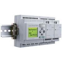
FL1B-B12RCA IDEC, FL1B-B12RCA Datasheet - Page 9

FL1B-B12RCA
Manufacturer Part Number
FL1B-B12RCA
Description
83C9515
Manufacturer
IDEC
Datasheet
1.FL1B-M08D2R2.pdf
(14 pages)
Specifications of FL1B-B12RCA
Peak Reflow Compatible (260 C)
No
Signal Input Type
AC/DC Voltage
Output Type
Relay
Supply Voltage Max
24V
No. Of Digital Inputs
8
Leaded Process Compatible
No
No. Of Digital Outputs
4
Rohs Compliant
No
www.idec.com
Operating Temperature
Storage Temperature
Relative Humidity
Rated As-interface Voltage
Reverse Polarity Protection
Current Draw
EMC
Vibration Resistance
Shock Resistance
Slave type
Profile
Degree of Protection
Terminal Style
Applicable wire
Instruction
Dimensions
Weight
Electrostatic
Discharge
Electromagnetic filed
First Transient
Burst Pulse
Radiated Emission
“n” depends on the plug-in position of the expansion module relative to the IDEC SmartRelay CPU. It indicates the number of
the input or output in the IDEC SmartRelay program code.
IDEC SmartRelay System
IDEC SmartRelay
Outputs:
Inputs:
Q
Q
Q
I
I
I
Q
n+1
n+2
n+3
In
n+1
n+
n+3
n
2
30 VDC (26.5VDC to 31.6VDC)
0 to 55°C
–40 to +70°C
10 to 85% (no condensation)
Yes
70 mA max.
8 kV air discharge (IEC61000-4-2)
4 kV contact discharge
Filed strength 10V/m (IEC61000-4-3)
1kV (criteria A) (IEC61000-4-4)
1kV (criteria B)
Class A (EN55011)
5 to 9 Hz, amplitude 3.5 mm
9 to 150 Hz, 9.8 m/s
147 m/s
Standard slave
I/O code 7
I/D code F
I/D2 code F
IP20
Screw terminal (tightening torque: max. 0.5Nm)
0.5 to 1.5mm
on a 35mm mounting rail according to DIN EN50022/wall mounting
36W 90H 58D mm
75g
USA: (800) 262-IDEC or (408) 747-0550, Canada: (888) 317-IDEC
2
11ms (X, Y, Z each direction 3 times)
2
2
Specifications con’t
Logic Assignments
AS-Interface System
Output data bits:
Input data bits:
D0
D1
D2
D3
D0
D1
D2
D3
Specifications
H-9
H


