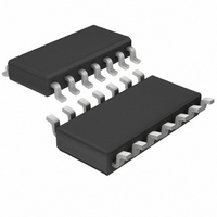
LT1684IS#TRPBF Linear Technology, LT1684IS#TRPBF Datasheet - Page 11

LT1684IS#TRPBF
Manufacturer Part Number
LT1684IS#TRPBF
Description
IC RING TONE GENERATOR 14-SOIC
Manufacturer
Linear Technology
Datasheet
1.LT1684CN.pdf
(16 pages)
Specifications of LT1684IS#TRPBF
Function
Tone Generator
Number Of Circuits
1
Operating Temperature
-40°C ~ 125°C
Mounting Type
Surface Mount
Package / Case
14-SOIC (3.9mm Width), 14-SOL
Lead Free Status / RoHS Status
Lead free / RoHS Compliant
Current - Supply
-
Voltage - Supply
-
Power (watts)
-
Interface
-
Available stocks
Company
Part Number
Manufacturer
Quantity
Price
APPLICATIO S I FOR ATIO
The LT1684 can be implemented easily into a telephone
ringer circuit based on the active filter tuned oscillator
topology, eliminating the need for a user-supplied PWM
input signal. The LT1684’s active filter amplifier can be
used as a high-Q bandpass filter element by configuring
it as an active tracking supply bandpass. The LT1684’s
controlled output receiver/buffer is also convenient for
use as the hard limiter. Because the LT1684 receiver/
buffer requires a true differential input for proper opera-
tion, a dual comparator IC such as the LT1017 must be
bootstrapped along with the LT1684 to provide differen-
tial control signals. The LT1017 and LT1684 receiver/
buffer combine to create a high gain hard limiter whose
Active Filter Tuned Oscillator Block Diagram
V
IN
+
–
Active Tracking Bandpass MFB Filter
R
R
F1
F1
C
F2
R
C
F2
F1
R
Bandpass MFB Filter
F2
U
C
F1
R
–
F3
V
U
C
IN
–
+
F2
+
–
+
R
F3
W
1684 F03
V
1684 F5b
OUT
V
1684 F4a
OUT
U
output is controlled to 1.25V. The LT1684 active
bandpass filter is then connected as a positive feedback
element with the limiter component, which completes
the active filter tuned oscillator topology.
The active bandpass filter circuit is easily configured using
a basic MFB bandpass configuration, however, the active
tracking supply technique used by the LT1684 requires
“transformation” of this topology. This “transformation”
swaps the amplifier signal polarity, references all signals
to the output, and references all feedback elements to
ground as described previously in the Filter Design and
Component Selection section.
The design equations for the active tracking bandpass
filter are the same as the pretransformation MFB topology,
such that if C
Example:
Conditions: Output peak voltage = 95V
A square wave with peak amplitude A has a fundamental
component with amplitude 4A/ , where A = 1.25V. There-
fore, the desired filter’s bandpass gain H
1.25/ ) ~ 60. Given capacitor values C = 0.22 F (a conve-
nient value) and desired filter characteristics of: Q = 9.4,
R
sponse time of the output signal can be adjusted by simply
changing the values of resistors R
This produces a high voltage, high quality 20Hz sine wave
at the filter output with a peak amplitude of 95V. Differen-
tial amplitude and frequency characteristics are achieved
by simply changing a few resistor values. The output of the
LT1684 is internally current limited to a minimum of
be used with loads up to 7 REN with no degradation of the
output waveform.
100mA peak, allowing this ring tone generation circuit to
H
F3
R
R
R
O
F1
F2
F3
= 680k. The amplitude, frequency and envelope re-
= 60,
= Q/(
= Q/(2Q
= 2Q/(
F1
Ring frequency = 20Hz
Bandpass Q = 9.4
O
O
2
O
• C • H
= C
= 2 (20Hz), then: R
– H
• C)
F2
0
= C:
0
)(
)
O
• C)
F1
F1
to R
= 5.6k, R
F3
LT1684
O
accordingly.
= 95/(4 •
F2
11
= 2.7k,


