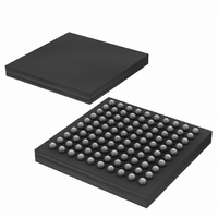
DS2155G Maxim Integrated Products, DS2155G Datasheet - Page 4

DS2155G
Manufacturer Part Number
DS2155G
Description
IC TXRX T1/E1/J1 1-CHIP 100CSBGA
Manufacturer
Maxim Integrated Products
Specifications of DS2155G
Function
Single-Chip Transceiver
Interface
E1, HDLC, J1, T1
Number Of Circuits
1
Voltage - Supply
3.14 V ~ 3.47 V
Current - Supply
75mA
Operating Temperature
0°C ~ 70°C
Mounting Type
Surface Mount
Package / Case
100-LFBGA
Includes
BERT Generator and Detector, CMI Coder and Decoder, HDLC Controller
Lead Free Status / RoHS Status
Contains lead / RoHS non-compliant
Power (watts)
-
Available stocks
Company
Part Number
Manufacturer
Quantity
Price
Part Number:
DS2155G+
Manufacturer:
MAXIM/美信
Quantity:
20 000
Company:
Part Number:
DS2155G+T&R
Manufacturer:
MAXIM
Quantity:
68
Company:
Part Number:
DS2155G+T&R
Manufacturer:
Maxim Integrated
Quantity:
10 000
Company:
Part Number:
DS2155G/T&R
Manufacturer:
Maxim Integrated
Quantity:
10 000
Part Number:
DS2155GN+
Manufacturer:
DALLAS
Quantity:
20 000
Company:
Part Number:
DS2155GNC2+T&R
Manufacturer:
MAXIM
Quantity:
14
8. HDLC SS7 SUPPORT
9. TCLK JITTER
10. T1 LINE BUILD OUT
11. FRAMER CRC ERROR COUNT
12. AUTOMATIC GAIN CONTROL ON TRANSMITTER
Description:
The SS7 support features “transmit loop” and “receive FISU discard” are not available in the DS2155
A3 revision.
Work Around:
There is no known software work around for this issue.
Description:
More than 0.1UI of jitter on the transmit clock (TCLK or TCLKI) can cause an isolated 1 to be
transmitted as a doubled 1. In normal operation this situation does not occur. If TCLK is derived from
RCLK, the jitter attenuator typically is in the receive path so jitter is far below 0.1UI. If an
independent TCLK source has jitter >0.05UI, the jitter attenuator must be placed in the transmit path.
Therefore, the transmit LIU should never see a transmit clock with more than 0.05UI of jitter.
Work Around:
Enable the jitter attenuator in the transmit path if using a system clock for TCLK, or the receive path
if using a recovered clock.
Description:
Line build outs 3 and 4 may not meet the short-haul template requirements.
Work Around:
There is no work around for line build outs 3 and 4.
Description:
The potential exists for the CRC error counter to miss a CRC error if it occurs on a timer boundary.
Work Around:
There is no known software work around for this issue.
Description:
The output pulse may not meet template in automatic gain-control mode.
Work Around:
Use the nonautomatic gain mode as described in the TLBC register in Section 25.7 of the data sheet.
4 of 7
DS2155 ERRATA SHEET


