PC16550DV/NOPB National Semiconductor, PC16550DV/NOPB Datasheet - Page 5
PC16550DV/NOPB
Manufacturer Part Number
PC16550DV/NOPB
Description
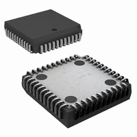
IC UART WITH FIFO 44-PLCC
Manufacturer
National Semiconductor
Specifications of PC16550DV/NOPB
Features
Modem Control Function
Number Of Channels
1, UART
Fifo's
16 Byte
Voltage - Supply
4.5 V ~ 5.5 V
With False Start Bit Detection
Yes
With Modem Control
Yes
Mounting Type
Surface Mount
Package / Case
44-LCC (J-Lead)
No. Of Channels
1
Data Rate
1.5Mbps
Uart Features
Independently Controlled Transmit, Receive, Line Status, And Data Set Interrupts
Supply Voltage Range
4.5V To 5.5V
Rohs Compliant
Yes
Lead Free Status / RoHS Status
Lead free / RoHS Compliant
Other names
*PC16550DV
*PC16550DV/NOPB
PC16550DV
*PC16550DV/NOPB
PC16550DV
Available stocks
Company
Part Number
Manufacturer
Quantity
Price
Company:

Part Number:
PC16550DV/NOPB
Manufacturer:
NSC
Quantity:
4 396
Company:
Part Number:
PC16550DV/NOPB
Manufacturer:
NVE
Quantity:
896
Company:
Part Number:
PC16550DV/NOPB
Manufacturer:
Texas Instruments
Quantity:
10 000


3 0 AC Electrical Characteristics
Note 1 This delay will be lengthened by 1 character time minus the last stop bit time if the transmitter interrupt delay circuit is active (See FIFO Interrupt Mode
Operation)
Note 2 These specifications are preliminary
4 0 Timing Waveforms
Note 1 The 2 4V and 0 4V levels are the voltages that the inputs are driven to during AC testing
Note 2 The 2 0V and 0 8V levels are the voltages at which the timing tests are made
Symbol
Transmitter
t
t
t
t
t
t
t
Modem Control
t
t
t
HR
IR
IRS
SI
STI
SXA
WXI
MDO
RIM
SIM
External Clock Input (24 0 MHz Max )
Delay from WR WR (WR THR)
to Reset Interrupt
Delay from RD RD (RD IIR) to Reset
Interrupt (THRE)
Delay from Initial INTR Reset to Transmit
Start
Delay from Initial Write to Interrupt
Delay from Stop to Interrupt (THRE)
Delay from Start to TXRDY active
Delay from Write to TXRDY inactive
Delay from WR WR (WR MCR) to
Output
Delay from RD RD to Reset Interrupt
(RD MSR)
Delay from MODEM Input to Set Interrupt
Parameter
(All timings are referenced to valid 0 and valid 1)
TL C 8652 – 2
BAUDOUT Timing
(Continued)
5
100 pF Load
100 pF Load
100 pF Load
100 pF Load
100 pF Load
100 pF Load
100 pF Load
Conditions
(Note 1)
(Note 1)
Min
AC Test Points
16
8
8
Max
175
250
195
200
250
250
24
24
8
8
TL C 8652 – 4
BAUDOUT
BAUDOUT
BAUDOUT
BAUDOUT
TL C 8652– 3
Cycles
Cycles
Cycles
Cycles
Units
ns
ns
ns
ns
ns
ns
Related parts for PC16550DV/NOPB
Image
Part Number
Description
Manufacturer
Datasheet
Request
R

Part Number:
Description:
UART IC
Manufacturer:
National Semiconductor
Datasheet:

Part Number:
Description:
National Semiconductor [8-Bit D/A Converter]
Manufacturer:
National Semiconductor
Datasheet:
Part Number:
Description:
National Semiconductor [Media Coprocessor]
Manufacturer:
National Semiconductor
Datasheet:
Part Number:
Description:
Digitally Controlled Tone and Volume Circuit with Stereo Audio Power Amplifier, Microphone Preamp Stage and National 3D Sound
Manufacturer:
National Semiconductor
Datasheet:
Part Number:
Description:
Digitally Controlled Tone and Volume Circuit with Stereo Audio Power Amplifier, Microphone Preamp Stage and National 3D Sound
Manufacturer:
National Semiconductor
Datasheet:
Part Number:
Description:
AC97 Rev 2 Codec with Sample Rate Conversion and National 3D Sound
Manufacturer:
National Semiconductor
Part Number:
Description:
Manufacturer:
National Semiconductor
Datasheet:
Part Number:
Description:
Manufacturer:
National Semiconductor
Datasheet:
Part Number:
Description:
General Purpose, Low Voltage, Low Power, Rail-to-Rail Output Operational Amplifiers
Manufacturer:
National Semiconductor
Datasheet:
Part Number:
Description:
8-bit 20 MSPS flash A/D converter.
Manufacturer:
National Semiconductor
Datasheet:
Part Number:
Description:
Low Noise Quad Operational Amplifier
Manufacturer:
National Semiconductor
Datasheet:
Part Number:
Description:
Quad Differential Line Receivers
Manufacturer:
National Semiconductor
Datasheet:
Part Number:
Description:
Quad High Speed Trapezoidal? Bus Transceiver
Manufacturer:
National Semiconductor
Datasheet:
Part Number:
Description:
Dual Line Receiver
Manufacturer:
National Semiconductor
Datasheet: