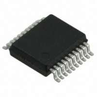
MCP2200-I/SS Microchip Technology, MCP2200-I/SS Datasheet - Page 7

MCP2200-I/SS
Manufacturer Part Number
MCP2200-I/SS
Description
IC USB TO UART 20SSOP
Manufacturer
Microchip Technology
Type
USB to UART Protocol Converterr
Specifications of MCP2200-I/SS
Package / Case
20-SSOP (0.200", 5.30mm Width)
Features
USB to UART
Number Of Channels
8
Fifo's
256 Byte
Protocol
USB 2.0
Voltage - Supply
3 V ~ 5.5 V
With Auto Flow Control
Yes
Mounting Type
Surface Mount
Mounting Style
SMD/SMT
Operating Temperature Range
- 40 C to + 85 C
Supply Current
13 mA
Operating Supply Voltage
3 V to 5.5 V
Usb Version
2.0
Data Rate
12Mbps
Supply Voltage Range
3V To 5.5V
Digital Ic Case Style
SSOP
No. Of Pins
20
Peak Reflow Compatible (260 C)
Yes
Rohs Compliant
Yes
Leaded Process Compatible
Yes
Lead Free Status / RoHS Status
Lead free / RoHS Compliant
Lead Free Status / RoHS Status
Lead free / RoHS Compliant, Lead free / RoHS Compliant
Available stocks
Company
Part Number
Manufacturer
Quantity
Price
Company:
Part Number:
MCP2200-I/SS
Manufacturer:
MICROCHIP
Quantity:
3 000
Part Number:
MCP2200-I/SS
Manufacturer:
MICROCHIP/微芯
Quantity:
20 000
1.7
The EEPROM module is a 256 byte array of nonvolatile
memory. The memory locations are accessed for read/
write operations via USB host commands. Refer to
Section 2.0 “Configuration” for details on accessing
the EEPROM.
The host should wait for the write cycle to complete and
then verify the write by reading the byte(s).
1.8
1.8.1
The RST pin provides a method for triggering an
external Reset of the device. A Reset is generated by
holding the pin low. These devices have a noise filter in
the reset path which detects and ignores small pulses.
1.8.2
A Power-on Reset pulse is generated on-chip
whenever V
allows the device to start in the initialized state when
V
To take advantage of the POR circuitry, tie the RST pin
through a resistor (1 kOhm to 10 kOhm) to V
will eliminate external RC components usually needed
to create a Power-on Reset delay.
When the device starts normal operation (i.e., exits the
Reset
(voltage, frequency, temperature, etc.) must be met to
ensure operation. If these conditions are not achieved,
the device must be held in Reset until the operating
conditions are met.
2010 Microchip Technology Inc.
DD
is adequate for operation.
condition),
EEPROM Module
RESET/POR
RESET PIN
POR
DD
rises above a certain threshold. This
device
operating
parameters
DD
. This
1.9
The input clock must be 12 MHz to provide the proper
frequency for the USB module.
USB full-speed is nominally 12 Mb/s. The clock input
accuracy is ±0.25% (2,500 ppm maximum).
FIGURE 1-3:
FIGURE 1-4:
Note 1: A series resistor (R
Oscillator
Quartz Crystal
2: The value of R
CSTCE12M0G15L
Example: muRata
12 MHz
for quartz crystals with high drive level.
2 M to 10 M.
Resonator
12 MHz
QUARTZ CRYSTAL
OPERATION
CERAMIC RESONATOR
OPERATION
R
S
(1)
MCP2200
F
OSC2
OSC1
is typically between
S
OSC2
) may be required
OSC1
R
MCP2200
MCP2200
F
(2)
DS22228A-page 7


