ISD5116EY Nuvoton Technology Corporation of America, ISD5116EY Datasheet - Page 27
ISD5116EY
Manufacturer Part Number
ISD5116EY
Description
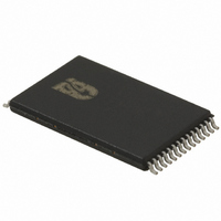
IC VOICE REC/PLAY 8-16MN 28-TSOP
Manufacturer
Nuvoton Technology Corporation of America
Series
ISD5100r
Datasheet
1.ISD5116SY.pdf
(90 pages)
Specifications of ISD5116EY
Interface
I²C
Filter Pass Band
1.7 ~ 3.4kHz
Duration
8 ~ 16 Min
Mounting Type
Surface Mount
Package / Case
28-TSOP
For Use With
ISD-ES511 - EVALUATION SYSTEM FOR ISD5100ISD-ES501 - EVALUATION SYSTEM FOR ISD5008
Lead Free Status / RoHS Status
Lead free / RoHS Compliant
Available stocks
Company
Part Number
Manufacturer
Quantity
Price
Company:

Part Number:
ISD5116EY
Manufacturer:
IDT
Quantity:
287


To set up the chip for Memo or Call Playback, the configuration registers are set up as follows:
Only those portions necessary for this mode are powered up.
Message cueing allows the user to skip through analog messages without knowing the actual physical
location of the message. This operation is used during playback. In this mode, the messages are
skipped 512 times faster than in normal playback mode. It will stop when an EOM marker is reached.
Then, the internal address counter will be pointing to the next message.
5. Select the SUM2 SUMMING amplifier path through the VOLUME MUX — Bits VLS0 and VLS1
6. Power up the VOLUME CONTROL LEVEL — Bit VLPD controls the power-up state of the
7. Select a VOLUME CONTROL LEVEL—Bits VOL0, VOL1, and VOL2 control the state of the
8. Select the VOLUME CONTROL path through the OUTPUT MUX — These are bits D3 and D4,
9. Power up the SPEAKER amplifier and select the HIGH GAIN mode — Bits OPA0 and OPA1
CFG0=0010 0100 0010 0100 (hex 2424).
CFG1=0101 1001 1101 0001 (hex 59D1).
control the state VOLUME MUX. These bits are bits D14 and D15, respectively of CFG1. They
should be set to the state where D14 is ONE and D15 is ZERO to select the SUM2 SUMMING
amplifier.
VOLUME CONTROL attenuator. This is Bit D0 of CFG0. This bit must be set to a ZERO to
power-up the VOLUME CONTROL.
VOLUME CONTROL LEVEL. These are bits D11, D12, and D13, respectively, of CFG1. A
binary count of 000 through 111 controls the amount of attenuation through that state. In most
cases, the software will select an attenuation level according to the desires of the current
users of the product. In this example, we will assume the user wants an attenuation of –12 dB.
For that setting, D11 should be set to ONE, D12 should be set to ONE, and D13 should be set
to a ZERO.
respectively, of CFG0. They should be set to the state where D3 is ZERO and D4 is a ZERO
to select the VOLUME CONTROL.
control the state of the speaker (SP+ and SP–) and AUX OUT outputs. These are bits D1 and
D2 of CFG0. They must be set to the state where D1 is ONE and D2 is ZERO to power-up the
speaker outputs in the HIGH GAIN mode and to power-down the AUX OUT.
6.3.11 Message Cueing
- 27 -
Publication Release Date: Oct 31, 2008
ISD5100 SERIES
Revision 1.42
Related parts for ISD5116EY
Image
Part Number
Description
Manufacturer
Datasheet
Request
R

Part Number:
Description:
MODULE FOR VOICE REC/PLAY 10S
Manufacturer:
Nuvoton Technology Corporation of America
Part Number:
Description:
Manufacturer:
Nuvoton Technology Corporation of America
Datasheet:
Part Number:
Description:
Manufacturer:
Nuvoton Technology Corporation of America
Datasheet:
Part Number:
Description:
Manufacturer:
Nuvoton Technology Corporation of America
Datasheet:
Part Number:
Description:
Manufacturer:
Nuvoton Technology Corporation of America
Datasheet:
Part Number:
Description:
Manufacturer:
Nuvoton Technology Corporation of America
Datasheet:
Part Number:
Description:
Manufacturer:
Nuvoton Technology Corporation of America
Datasheet: