1-2013496-1 TE Connectivity, 1-2013496-1 Datasheet - Page 6
1-2013496-1
Manufacturer Part Number
1-2013496-1
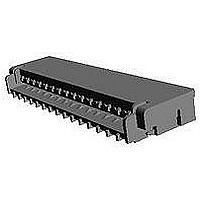
Description
FFC / FPC Connectors 0.3MM 31POS FPC/FCC LCP HSG
Manufacturer
TE Connectivity
Specifications of 1-2013496-1
Product Type
PCB
Pitch
0.3 mm
Number Of Positions / Contacts
31
Mounting Angle
Right
Mounting Style
SMD/SMT
Actuation Type
ZIF
Contact Location
Bottom Contact
Termination Style
Solder Pin
Wire Type
FPC
Termination Method To Pc Board
Surface Mount
Pcb Mounting Orientation
Right Angle
Pcb Mount Alignment
Without
Pcb Mount Retention
With
Actuator Type
Rear Flip (Front Hinge)
Shrouded
Yes
Sealed
No
Strain Relief
Without
Contact Current Rating, Max (a)
0.2
Operating Voltage Reference
AC
Operating Voltage (vac)
50
Shielded
No
Tail Orientation
Staggered
Profile Height (y-axis) (mm [in])
1.20 [0.047]
Centerline (mm [in])
0.30 [0.012]
Number Of Positions
31
Selectively Loaded
No
Pcb Mount Retention Type
Solder Pads
Length (x-axis) (mm [in])
11.10 [0.437]
Width (z-axis) (mm [in])
2.90 [0.114]
Contact Plating, Mating Area, Material
Gold
Contact Plating, Mating Area, Thickness (µm [?in])
0.1 [3.937]
Tail Plating Material
Gold
Tail Plating, Thickness (µm [?in])
0.1 [3.93]
Contact Design
Single Beam
Housing Material
Liquid Crystal Polymer (LCP)
Contact Mating Location
Bottom
Flex Cable Thickness (mm [in])
0.2 [0.008]
Housing Color
Beige
Rohs/elv Compliance
RoHS compliant, ELV compliant
Lead Free Solder Processes
Reflow solder capable to 245°C
Rohs/elv Compliance History
Always was RoHS compliant
Circuit Identification Feature
Without
Operating Temperature (°c [°f])
-25 – +85 [-13 – +185]
Zif/non-zif
ZIF
Contact Transmits (typical Application)
Signal (Data)
Pick And Place Cover
Without
Packaging Method
Tape & Reel


3.5.12
3.5.12
3.5.13
3.5.13
3.5.14
3.5.14
3.5.15
3.5.15
Rev. C
Para.
項目
はんだ耐熱性
Resistance to Soldering
Heat
耐寒性
Resistance to Cold
耐熱性
Temperature Life
耐湿性
(定常状態)
Humidity
(Steady State)
Test Items
試験項目
電気的及び機械的性能を満足す
ること。
外観に異常なきこと。
Connector to function as
specified electrical and
mechanical requirements after
test.
No physical damage allowed.
総合抵抗:100mΩ以下 (終期)
外観に異常なきこと。
Termination Resistance:
No physical damage allowed.
総合抵抗:100mΩ以下 (終期)
外観に異常なきこと。
Termination Resistance:
No physical damage allowed.
総合抵抗:100mΩ以下 (終期)
絶縁抵抗:50MΩ以上(終期)
Termination Resistance:
Insulation resistance:
Product Specification
Environmental Requirements
Fig. 1 (続く) Fig. 1 (CONT.)
規
Requirements
環 境 的 性 能
100mΩMax(Final)
100mΩMax(Final)
100mΩMax(Final)
50MΩMin(Final)
格
値
温度プロファイルはFig.2参照
ピーク:250(+5/-0)℃
はんだ付けゾ-ン230℃以上,30±10秒
手はんだの場合
温度:350±10℃, 時間:3+1/-0秒
Temperature profile : as shown in Fig.2
Peak 250(+5/-0)℃ Soldering zone 230℃ or
higher ,30±10sec.
Hand Soldering
Temperature:350±10℃, Time:3+1/-0sec.
嵌合したコネクタを-25±3℃へ48時間放
置後、常温中に1時間放置し測定する。
Mated Connector shall be stored at
temperature of -25±3°C for 48hr. Then
in shall be subjected to standard
atmospheric condition for 1hr, after
which measurement shall be made.
嵌合したコネクタを85±2℃へ96時間放置
後、常温中に1時間放置し測定する。
Mated Connector shall be stored at
temperature of 85±2°C for 96hr. Then in
shall be subjected to standard
atmospheric condition for 1hr, after
which measurement shall be made.
嵌合したコネクタを40±2℃、90~95%R.H
へ96時間放置後、常温中に1時間放置し測
定する。
Mated Connector shall be stored at
temperature of 40±2℃ with relative
humidity 90~95%R.H. for 96hr. Then in
shall be subjected to standard
atmospheric condition for 1hr, after
which measurement shall be made.
試
Procedures
験
108-78351
方
6 of 10
法
Related parts for 1-2013496-1
Image
Part Number
Description
Manufacturer
Datasheet
Request
R


Part Number:
Description:
CONNECTOR, SMT-IDC, 2 POS, 20 AWG
Manufacturer:
TE Connectivity
Datasheet:

Part Number:
Description:
CONTACT, RECEPTACLE, 20-16AWG, CRIMP
Manufacturer:
TE Connectivity
Datasheet:
Part Number:
Description:
CONTACT, RECEPTACLE, 20-16AWG, CRIMP
Manufacturer:
TE Connectivity
Datasheet:

Part Number:
Description:
Headers & Wire Housings RECPT 24-20 AWG 30 AU
Manufacturer:
TE Connectivity
Datasheet:

Part Number:
Description:
Manufacturer:
TE Connectivity
Datasheet:

Part Number:
Description:
Manufacturer:
TE Connectivity
Datasheet:

Part Number:
Description:
Manufacturer:
TE Connectivity
Datasheet:

Part Number:
Description:
Manufacturer:
TE Connectivity
Datasheet:

Part Number:
Description:
CONNECTOR, SMT-IDC PASS THRU, 2 POS, 20
Manufacturer:
TE Connectivity
Datasheet:

Part Number:
Description:
Conn D-Subminiature PL 9 POS 2.74mm Solder RA Thru-Hole 9 Terminal 1 Port
Manufacturer:
TE Connectivity
Datasheet:

Part Number:
Description:
Conn D-Subminiature RCP 9 POS 2.74mm Solder RA Thru-Hole 9 Terminal 1 Port
Manufacturer:
TE Connectivity
Datasheet:

Part Number:
Description:
Conn D-Subminiature RCP 9 POS 2.77mm Solder ST Thru-Hole 9 Terminal 1 Port Tray
Manufacturer:
TE Connectivity
Datasheet:

Part Number:
Description:
FFC/FPC CONNECTOR, RECEPTACLE 12POS 1ROW
Manufacturer:
TE Connectivity
Datasheet:

Part Number:
Description:
Manufacturer:
TE Connectivity
Datasheet: