53892-7 TE Connectivity, 53892-7 Datasheet - Page 8
53892-7
Manufacturer Part Number
53892-7
Description
Power to the Board CONTACT CRIMP 18-12 Series 1
Manufacturer
TE Connectivity
Series
Series Ir
Specifications of 53892-7
Product Type
Contacts
Termination Style
Crimp
Contact Plating
Gold (30)
Contact Material
Copper
Wire Gauge Range
18-12
Wire Size (awg)
18-12
Termination Method To Wire/cable
Crimp
Ul File Number
E28476
Csa File Number
LR7189
Wire/cable Type
Discrete Wire
Make First / Break Last
No
Contact - Rated Current (a)
31
Operating Voltage Reference
AC
Operating Voltage (vac)
600
Wire/cable Size (awg)
12 – 18
Wire/cable Size (mm²)
0.811 – 3.09
Wire/cable Size (cma)
1,601 – 6,098
Profile Height (y-axis) (mm [in])
3.05 [0.120]
Length (x-axis) (mm [in])
18.29 [0.720]
Width (z-axis) (mm [in])
3.76 [0.148]
Underplate Material Thickness (µm [?in])
1.27 [50.000]
Contact Type
Pin/Socket
Contact Plating, Mating Area, Material
Gold
Contact Plating, Mating Area, Thickness (µm [?in])
0.762 [30]
Contact Base Material
Copper
Contact Design
Spring Latch
Underplate Material
Nickel
Rohs/elv Compliance
RoHS compliant, ELV compliant
Lead Free Solder Processes
Not relevant for lead free process
Rohs/elv Compliance History
Always was RoHS compliant
Vde Tested
No
Agency/standard
UL, CSA
Ul Rating
Recognized
Csa Certified
Yes
Operating Temperature (°c [°f])
-40 – +75 [-40 – +167]
Applies To
Wire/Cable
Accepts Wire Insulation Diameter, Range (mm [in])
0.864 – 0.914 [0.034 – 0.036]
Accepts Wire Material
Copper
Application Use
Wire-to-Wire
Contact Transmits (typical Application)
Power
Packaging Method
Loose Piece
Lead Free Status / Rohs Status
Details


Rev B
NOTE
NOTE
(a)
(b)
(a)
(b)
(c)
Unless specifically permitted within NEC, overcurrent protection for the following conductor
types shall not be exceeded.
1.
2.
3.
4.
To determine acceptable current carrying capacity for percentage connector loading and wire
gage indicated, use Multiplication Factor (F) from above chart and multiply it times Base
Rated Current for a single circuit at maximum ambient operating temperature as shown in
Figure 5A.
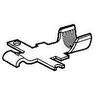
Thermocouples shall be spot welded to contact near intersection of tongue and barrel as
shown and coated with thermal conductive epoxy.
Thermocouple shall exit housing by running down side of wire barrel.
Printed circuit board shall be modified to allow thermocouple wire to pass through boards.
7 amperes for 18 AW G copper wire
10 amperes for 16 AW G copper wire
15 amperes for 14 AW G copper wire
20 amperes for 12 AW G copper wire
Percent Connector
Single Contact
Loading
100
50
Therm ocouple Mounting
Current Rating
Figure 5B
Figure 6
.56
.51
.43
18
W ire Size AW G
.71
.64
.55
16
.85
.66
.78
14
.91
.78
12
1
108-11026
8 of 9
Related parts for 53892-7
Image
Part Number
Description
Manufacturer
Datasheet
Request
R

Part Number:
Description:
CONTACT, 18-12AWG, CRIMP
Manufacturer:
TE Connectivity
Datasheet:

Part Number:
Description:
Power to the Board CONTACT PWR LK
Manufacturer:
TE Connectivity
Datasheet:
Part Number:
Description:
CONTACT,PWR LK,SRS1,STRIP,CRMP
Manufacturer:
TE Connectivity
Datasheet:

Part Number:
Description:
Printers THERMAL PRINTER HS-SLEEVE MARKER
Manufacturer:
TE Connectivity


Part Number:
Description:
High Speed / Modular Connectors 30P HEADER ASSY
Manufacturer:
TE Connectivity
Datasheet:

Part Number:
Description:
High Speed / Modular Connectors REC 6X005P R/A LT B-PLANE HS3
Manufacturer:
TE Connectivity
Datasheet:

Part Number:
Description:
High Speed / Modular Connectors 2MM HM RCPT 50P R/A AU
Manufacturer:
TE Connectivity
Datasheet:

Part Number:
Description:
High Speed / Modular Connectors 2MM HM RCPT 50P R/A AU
Manufacturer:
TE Connectivity
Datasheet:


Part Number:
Description:
Manufacturer:
TE Connectivity
Datasheet:


Part Number:
Description:
Manufacturer:
TE Connectivity
Datasheet:

Part Number:
Description:
Manufacturer:
TE Connectivity
Datasheet:

Part Number:
Description:
Manufacturer:
TE Connectivity
Datasheet: