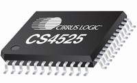
CS4525-CNZ Cirrus Logic Inc, CS4525-CNZ Datasheet - Page 18

CS4525-CNZ
Manufacturer Part Number
CS4525-CNZ
Description
IC AMP AUDIO PWR 30W QUAD 48QFN
Manufacturer
Cirrus Logic Inc
Series
Popguard®r
Type
Class Dr
Datasheet
1.CS4525-CNZ.pdf
(98 pages)
Specifications of CS4525-CNZ
Output Type
2-Channel (Stereo) or 4-Channel (Quad)
Package / Case
48-QFN
Max Output Power X Channels @ Load
30W x 1 @ 4 Ohm; 15W x 2 @ 8 Ohm
Voltage - Supply
8 V ~ 18 V
Features
ADC, Depop, I²C, I²S, Mute, PWM, Short-Circuit and Thermal Protection, Volume Control
Mounting Type
Surface Mount
Product
Class-D
Output Power
30 W
Thd Plus Noise
10 %
Operating Supply Voltage
2.5 V to 5 V
Supply Current
54 mA
Maximum Power Dissipation
180 mW
Maximum Operating Temperature
+ 70 C
Mounting Style
SMD/SMT
Audio - Load Impedance
4 Ohms, 6 Ohms, 8 Ohms
Audio Load Resistance
8 Ohms, 4 Ohms
Minimum Operating Temperature
0 C
Supply Voltage (max)
5.25 V
Supply Voltage (min)
2.375 V
Amplifier Class
D
No. Of Channels
4
Supply Voltage Range
8V To 18V
Load Impedance
4ohm
Operating Temperature Range
0°C To +70°C
Amplifier Case Style
QFN
No. Of Pins
48
Rohs Compliant
Yes
Lead Free Status / RoHS Status
Lead free / RoHS Compliant
For Use With
598-1586 - REFERENCE BOARD FOR CS4525 PWM
Lead Free Status / Rohs Status
Lead free / RoHS Compliant
Other names
598-1264
Available stocks
Company
Part Number
Manufacturer
Quantity
Price
Company:
Part Number:
CS4525-CNZ
Manufacturer:
CRYSTAL
Quantity:
329
Part Number:
CS4525-CNZ
Manufacturer:
TI/德州仪器
Quantity:
20 000
Part Number:
CS4525-CNZR
Manufacturer:
CIRRUSLOGICINC
Quantity:
20 000
18
5. CHARACTERISTICS AND SPECIFICATIONS
RECOMMENDED OPERATING CONDITIONS
AGND = DGND = PGND = 0 V; all voltages with respect to ground.
Notes:
ABSOLUTE MAXIMUM RATINGS
AGND = DGND = PGND = 0 V; all voltages with respect to ground.
Notes:
WARNING: Operation beyond these limits may result in permanent damage to the device. Normal operation is not
DC Power Supply
Digital and Analog Core
Amplifier Outputs
Temperature
Ambient Temperature
Junction Temperature
DC Power Supply
Power Stage
Power Stage
Digital and Analog Core
Inputs
Input Current
Analog Input Voltage
Digital Input Voltage
Temperature
Ambient Operating Temperature - Power Applied
Storage Temperature
1. For VD = 2.5 V, VA_REG and VD_REG must be connected to VD. See
2. Any pin except supplies. Transient currents of up to ±100 mA on the analog input pins will not cause
3. The maximum over/under voltage is limited by the input current.
guaranteed at these extremes.
details.
SCR latch-up.
Parameters
Parameters
Outputs Switching and Under Load
No Output Switching
Commercial
Commercial
(Note 2)
(Note 3)
(Note 3)
(Note 1)
Symbol
Symbol
V
V
T
VP
VP
VD
T
VD
VD
VD
VP
I
T
INA
IND
T
stg
in
A
A
J
2.375
3.135
AGND - 0.7
4.75
Min
-10
-10
8.0
Min
-0.3
-0.3
-0.3
-0.3
-20
-65
-
section 6.7 on page 63
Nom
2.5
3.3
5.0
-
-
-
VA_REG + 0.7
VD + 0.4
+150
2.625
3.465
Max
19.8
23.0
Max
+125
+85
5.25
18.0
±10
+70
6.0
CS4525
DS726PP2
Units
Units
°C
°C
V
V
V
V
mA
°C
°C
V
V
V
V
V
for


