TDA2050V STMicroelectronics, TDA2050V Datasheet - Page 5
TDA2050V
Manufacturer Part Number
TDA2050V
Description
IC AMP AUDIO PWR HIFI PENTAWATT5
Manufacturer
STMicroelectronics
Type
Class ABr
Datasheet
1.TDA2050V.pdf
(13 pages)
Specifications of TDA2050V
Output Type
1-Channel (Mono)
Max Output Power X Channels @ Load
35W x 1 @ 4 Ohm
Voltage - Supply
9 V ~ 50 V, ±4.5 V ~ 25 V
Features
Short-Circuit and Thermal Protection
Mounting Type
Through Hole
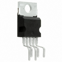
Package / Case
Pentawatt-5 (Vertical, Bent and Staggered Leads)
Product
Class-AB
Output Power
50 W
Available Set Gain
80 dB
Thd Plus Noise
0.03 %
Operating Supply Voltage
25 V
Supply Current
90 mA
Maximum Power Dissipation
25000 mW
Maximum Operating Temperature
+ 150 C
Mounting Style
Through Hole
Audio Load Resistance
8 Ohms
Dual Supply Voltage
+/- 5 V, +/- 9 V, +/- 12 V, +/- 15 V, +/- 18 V, +/- 24 V
Input Bias Current (max)
0.5 uA
Input Offset Voltage
15 mV
Input Signal Type
Differential
Minimum Operating Temperature
- 40 C
Output Signal Type
Single
Supply Type
Dual
Amplifier Class
AB
No. Of Channels
1
Supply Voltage Range
± 4.5V To ± 25V
Load Impedance
4ohm
Operating Temperature Range
-40°C To +150°C
Rohs Compliant
Yes
Lead Free Status / RoHS Status
Lead free / RoHS Compliant
Other names
497-3028-5
Available stocks
Company
Part Number
Manufacturer
Quantity
Price
Company:

Part Number:
TDA2050V
Manufacturer:
MICRON
Quantity:
11 560
Part Number:
TDA2050V
Manufacturer:
ST
Quantity:
20 000


SPLIT SUPPLY APPLICATION SUGGESTIONS
The recommended values of the external compo-
nents are those shown on the application circuit
(*) The gain must be higher than 24dB
PRINTED CIRCUIT BOARD
The layout shown in fig. 2 should be adopted by
the designers. If different layouts are used, the
Component
R1
R2
R3
R4
C1
C2
C3
C4
C5
C6
C7
Recommended
0.47 F
220 F
100nF
Value
680
22k
22k
22 F
2.2
1 F
Input Impedance
Feedback Resistor
Frequency Stability
Input Decoupling DC
Inverting Input
DC Decoupling
Supply Voltage Bypass
Supply Voltage Bypass
Frequency Stability
Purpose
Increase of Input
Impedance
Decrease of Gain (*)
Increase of Gain
Danger of Oscillations
Increase of Switch
ON/OFF Noise
of fig. 2. Different values can be used. The follow-
ing table can help the designer.
ground points of input 1 and input 2 must be well
decoupled from the ground return of the output in
which a high current flows.
Recommended Value
Larger than
Decrease of Input
Impedance
Decrease of Gain (*)
Higher Low-frequency
cut-off
Higher Low-frequency
cut-off
Danger of Oscillations
Danger of Oscillations
Danger of Oscillations
Increase of Gain
Recommended Value
Smaller than
TDA2050
5/13
Related parts for TDA2050V
Image
Part Number
Description
Manufacturer
Datasheet
Request
R

Part Number:
Description:
STMicroelectronics [RIPPLE-CARRY BINARY COUNTER/DIVIDERS]
Manufacturer:
STMicroelectronics
Datasheet:
Part Number:
Description:
STMicroelectronics [LIQUID-CRYSTAL DISPLAY DRIVERS]
Manufacturer:
STMicroelectronics
Datasheet:

Part Number:
Description:
BOARD EVAL FOR MEMS SENSORS
Manufacturer:
STMicroelectronics
Datasheet:
Part Number:
Description:
NPN TRANSISTOR POWER MODULE
Manufacturer:
STMicroelectronics
Datasheet:
Part Number:
Description:
TURBOSWITCH ULTRA-FAST HIGH VOLTAGE DIODE
Manufacturer:
STMicroelectronics
Datasheet:
Part Number:
Description:
Manufacturer:
STMicroelectronics
Datasheet:
Part Number:
Description:
DIODE / SCR MODULE
Manufacturer:
STMicroelectronics
Datasheet:
Part Number:
Description:
DIODE / SCR MODULE
Manufacturer:
STMicroelectronics
Datasheet:
Part Number:
Description:
Search -----> STE16N100
Manufacturer:
STMicroelectronics
Datasheet:
Part Number:
Description:
Search ---> STE53NA50
Manufacturer:
STMicroelectronics
Datasheet:
Part Number:
Description:
NPN Transistor Power Module
Manufacturer:
STMicroelectronics
Datasheet:
Part Number:
Description:
DIODE / SCR MODULE
Manufacturer:
STMicroelectronics
Datasheet: