TDA7360 STMicroelectronics, TDA7360 Datasheet - Page 25
TDA7360
Manufacturer Part Number
TDA7360
Description
IC AMP AUDIO PWR 22W MULTIWATT11
Manufacturer
STMicroelectronics
Type
Class ABr
Datasheet
1.TDA7360.pdf
(30 pages)
Specifications of TDA7360
Output Type
1-Channel (Mono) or 2-Channel (Stereo)
Max Output Power X Channels @ Load
22W x 1 @ 3.2 Ohm; 12W x 2 @ 1.6 Ohm
Voltage - Supply
8 V ~ 18 V
Features
Depop, Short-Circuit and Thermal Protection, Standby
Mounting Type
Through Hole
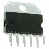
Package / Case
Multiwatt-11 (Vertical, Bent and Staggered Leads)
Operational Class
Class-AB
Output Power (typ)
22W
Audio Amplifier Function
Speaker
Total Harmonic Distortion
0.05%%
Single Supply Voltage (typ)
9/12/15V
Dual Supply Voltage (typ)
Not RequiredV
Power Supply Requirement
Single
Power Dissipation
36W
Rail/rail I/o Type
No
Power Supply Rejection Ratio
62dB
Single Supply Voltage (min)
8V
Single Supply Voltage (max)
18V
Dual Supply Voltage (min)
Not RequiredV
Dual Supply Voltage (max)
Not RequiredV
Operating Temp Range
-40C to 150C
Operating Temperature Classification
Automotive
Mounting
Through Hole
Pin Count
11 +Tab
Package Type
MULTIWATT V
Lead Free Status / RoHS Status
Lead free / RoHS Compliant
Other names
497-3973-5
Available stocks
Company
Part Number
Manufacturer
Quantity
Price

Part Number:
TDA7360
Manufacturer:
ST
Quantity:
20 000


TDA7360
4.4
Global approach to solving pop problem by using the
muting/turn-on delay function
In the real case turn-on and turn-off pop problems are generated not only by the power
amplifier, but also (very often) by preamplifiers, tone controls, radios etc. and transmitted by
the power amplifier to the loudspeaker.
A simple approach to solving these problems is to use the mute characteristics of the
TDA7360. If the SVR pin is at a voltage below 1.5 V, the mute attenuation (typ) is 30dB.The
amplifier is in play mode when V
With the circuit of
a time Toff after switch-off. During this period the circuitry that precedes the power amplifier
can produce spurious spikes that are not transmitted to the loudspeaker.
This can give back a very simple design of this circuitry from the pop point of view. A timing
diagram of this circuit is illustrated in
●
●
Figure 42. ST-BY pin supply circuit, example 1
Figure 43. ST-BY pin supply circuit, example 2
A reduced time constant allowance of stand-by pin turn off. Consequently it is possible
to drive all the car-radio with the signal that drives this pin.
A better turn-off noise with signal on the output. To drive two stereo amplifiers with this
circuit it is possible to use the circuit of
Figure 44
we can mute the amplifier for a time Ton after switch-on and for
Doc ID 1499 Rev 3
svr
overcomes 3.5 V.
Figure
Figure
45. Other advantages of this circuit are:
46.
Application hints
25/30
Related parts for TDA7360
Image
Part Number
Description
Manufacturer
Datasheet
Request
R

Part Number:
Description:
STMicroelectronics [RIPPLE-CARRY BINARY COUNTER/DIVIDERS]
Manufacturer:
STMicroelectronics
Datasheet:
Part Number:
Description:
STMicroelectronics [LIQUID-CRYSTAL DISPLAY DRIVERS]
Manufacturer:
STMicroelectronics
Datasheet:

Part Number:
Description:
BOARD EVAL FOR MEMS SENSORS
Manufacturer:
STMicroelectronics
Datasheet:
Part Number:
Description:
NPN TRANSISTOR POWER MODULE
Manufacturer:
STMicroelectronics
Datasheet:
Part Number:
Description:
TURBOSWITCH ULTRA-FAST HIGH VOLTAGE DIODE
Manufacturer:
STMicroelectronics
Datasheet:
Part Number:
Description:
Manufacturer:
STMicroelectronics
Datasheet:
Part Number:
Description:
DIODE / SCR MODULE
Manufacturer:
STMicroelectronics
Datasheet:
Part Number:
Description:
DIODE / SCR MODULE
Manufacturer:
STMicroelectronics
Datasheet:
Part Number:
Description:
Search -----> STE16N100
Manufacturer:
STMicroelectronics
Datasheet:
Part Number:
Description:
Search ---> STE53NA50
Manufacturer:
STMicroelectronics
Datasheet:
Part Number:
Description:
NPN Transistor Power Module
Manufacturer:
STMicroelectronics
Datasheet:
Part Number:
Description:
DIODE / SCR MODULE
Manufacturer:
STMicroelectronics
Datasheet: