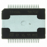
STA50613TR STMicroelectronics, STA50613TR Datasheet - Page 8

STA50613TR
Manufacturer Part Number
STA50613TR
Description
IC AMP AUDIO 40V QUAD POWERSO36
Manufacturer
STMicroelectronics
Type
Class Dr
Datasheet
1.STA50613TR.pdf
(14 pages)
Specifications of STA50613TR
Output Type
1-Channel (Mono) or 2-Channel (Stereo)
Max Output Power X Channels @ Load
120W x 1 @ 4 Ohm; 60W x 2 @ 8 Ohm
Voltage - Supply
10 V ~ 36 V
Features
Digital Inputs, Short-Circuit and Thermal Protection, Standby
Mounting Type
Surface Mount
Package / Case
PowerSO-36 Exposed Top Pad
Lead Free Status / RoHS Status
Lead free / RoHS Compliant
Other names
497-8857-2
STA50613TR
STA50613TR
Available stocks
Company
Part Number
Manufacturer
Quantity
Price
Company:
Part Number:
STA50613TR
Manufacturer:
MOTOROLA
Quantity:
250
Part Number:
STA50613TR
Manufacturer:
ST
Quantity:
20 000
STA506
3.3 Power Outputs:
The STA506 power and output pins are duplicated to provide a low impedance path for the device's bridged
outputs .
All duplicate power, ground and output pins must be connected for proper operation.
The PWRDN or TRI-STATE pins should be used to set all MOSFETS to the Hi-Z state during power-up until the
logic power supply, V
3.4 Parallel Output / High Current Operation:
When using DDX Mode output , the STA506 outputs can be connected in parallel in order to increase the output
current capability to a load.
In this configuration the STA506 can provide 80W into 8 ohm or up to 120W into 4ohm.
This mode of operation is enabled with the CONFIG pin (pin.24) connected to VREG1 and the inputs combined
INLA=INLB, INRA=INRB and the outputs combined OUTLA=OTLB, OUTRA=OUTRB.
3.5 Additional Informations:
Output Filter: A passive 2nd-order passive filter is used on the STA506 power outputs to reconstruct an analog
Audio Signal .
System performance can be significantly affected by the output filter design and choice of passive components.
A filter design for 6ohm/8ohm loads is shown in the Typical Application circuit of fig.1. Figure 9 shows a filter
design suitable for 4ohm loads.
Figure 10 shows a filter for ½ bridge mode , 4 ohm loads.
Power Dissipation & Heat Sink requirements: The power dissipated within the device will depend primarily
on the supply voltage, load impedance and output modulation level.
The PowerSO36 package of the STA506 includes an exposed thermal slug on the top of the device to provide
a direct thermal path from the IC to the heatsink.
Careful consideration must be given to the overall thermal design . See figure 8 for power derating
versus Slug temperature using different heatsinks and considering the Rth-jc =1.5°C/W.
8/14
– 1) SHUTDOWN mode: with FAULT (pull-up resistor) and TRI-STATE pins independent, an activated
– 2) AUTOMATIC recovery mode: This is shown in the Application Circuit of fig.1.
fault will disable the device, signaling low at the FAULT output.
The device may subsequently be reset to normal operation by toggling the TRI-STATE pin from
High to Low to High using an external logic signal.
The FAULT and TRI-STATE pins are shorted together and connected to a time constant circuit com-
prising R59 and C58.
An activated FAULT will force a reset on the TRI-STATE pin causing normal operation to resume fol-
lowing a delay determined by the time constant of the circuit.
If the fault condition is still present , the circuit operation will continue repeating until the fault condition
is removed .
An increase in the time constant of the circuit will produce a longer recovery interval. Care must be
taken in the overall system design as not to exceed the protection thesholds under normal operation.
L
, is settled.


