LM49350RL/NOPB National Semiconductor, LM49350RL/NOPB Datasheet - Page 43
LM49350RL/NOPB
Manufacturer Part Number
LM49350RL/NOPB
Description
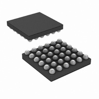
IC AUDIO SUBSYSTM 2W D 36USMDXT
Manufacturer
National Semiconductor
Series
Boomer®r
Type
Class Dr
Datasheet
1.LM49350RLNOPB.pdf
(104 pages)
Specifications of LM49350RL/NOPB
Output Type
1-Channel (Mono) with Mono and Stereo Headphones
Max Output Power X Channels @ Load
2W x 1 @ 4 Ohm; 69mW x 2 @ 32 Ohm
Voltage - Supply
2.7 V ~ 5.5 V
Features
3D, DAC, Depop, I²C, I²S, Mute, Short-Circuit and Thermal Protection, Shutdown, Volume Control
Mounting Type
Surface Mount
Package / Case
36-MicroSMDxt
Lead Free Status / RoHS Status
Lead free / RoHS Compliant
Other names
LM49350RLTR


20.4 HEADPHONE AMPLIFIER FUNCTION
The LM49350 headphone amplifier features National’s
ground referenced architecture that eliminates the large DC-
blocking capacitors required at the outputs of traditional head-
phone amplifiers. A low-noise inverting charge pump creates
a negative supply (HP_V
(LS_V
bipolar supplies, with the amplifier outputs biased about GND,
instead of a nominal DC voltage (typically V
tional amplifiers. Because there is no DC component to the
headphone output signals, the large DC-blocking capacitors
(typically 220μF) are not necessary, conserving board space
and system cost, while improving frequency response.
20.5 CHARGE PUMP CAPACITOR SELECTION
Use low ESR ceramic capacitors (less than 100mΩ) for opti-
mum performance.
Bits
Bits
0
1
2
3
4
5
0
1
2
3
4
5
DD
). The headphone amplifiers operate from these
DACR_HPL
AUXR_HPL
DACL_HPL
AUXL_HPL
MICR_HPL
MICL_HPL
DACR_HPR
AUXR_HPR
DACL_HPR
AUXL_HPR
MICR_HPR
MICL_HPR
Field
Field
SS
) from the positive supply voltage
The right DAC output is added to the left headphone output.
The left DAC output is added to the left headphone output.
The right MIC input is added to the left headphone output. Setting this bit enables MIC BIAS.
The left MIC input is added to the left headphone output. Setting this bit enables MIC BIAS.
The right AUX input is added to the left headphone output.
The left AUX input is added to the left headphone output.
FIGURE 15. EMI/RFI Filter for the Class D Amplifier
TABLE 20. RIGHT HEADPHONE_OUTPUT (0x12h)
TABLE 19. LEFT HEADPHONE_OUTPUT (0x11h)
The right DAC output is added to the right headphone output.
The left DAC output is added to the right headphone output.
The right MIC input is added to the right headphone output. Setting this bit enables the MIC
BIAS output.
The left MIC input is added to the right headphone output. Setting this bit enables the MIC
BIAS output.
The right AUX input is added to the right headphone output.
The left AUX input is added to the right headphone output.
DD
/2), like tradi-
43
20.6 CHARGE PUMP FLYING CAPACITOR (C6)
The flying capacitor (C6) affects the load regulation and out-
put impedance of the charge pump. A C6 value that is too low
results in a loss of current drive, leading to a loss of amplifier
headroom. A higher valued C6 improves load regulation and
lowers charge pump output impedance to an extent. Above
2.2μF, the R
of C6 and C5 dominate the output impedance. A lower value
capacitor can be used in systems with low maximum output
power requirements. Please refer to the demonstration board
schematic shown in Figure 23.
20.7 CHARGE PUMP FLYING CAPACITOR (C5)
The value and ESR of the hold capacitor (C5) directly affects
the ripple on CPV
put ripple. Decreasing the ESR of C5 reduces both output
ripple and charge pump output impedance. A lower value ca-
pacitor can be used in systems with low maximum output
Description
Description
DS(ON)
SS
of the charge pump switches and the ESR
. Increasing the value of C5 reduces out-
20194110
www.national.com
Related parts for LM49350RL/NOPB
Image
Part Number
Description
Manufacturer
Datasheet
Request
R

Part Number:
Description:
Manufacturer:
National Semiconductor
Datasheet:

Part Number:
Description:
High Performance Audio Codec Sub-system With A Ground-referenced Stereo Headphone Amplifier & An Ultra Low Emi Class D Loudspeaker Amplifier With Dual I2s/pcm Digital Audio Interfaces
Manufacturer:
National Semiconductor Corporation
Datasheet:
Part Number:
Description:
National Semiconductor [8-Bit D/A Converter]
Manufacturer:
National Semiconductor
Datasheet:
Part Number:
Description:
National Semiconductor [Media Coprocessor]
Manufacturer:
National Semiconductor
Datasheet:
Part Number:
Description:
Digitally Controlled Tone and Volume Circuit with Stereo Audio Power Amplifier, Microphone Preamp Stage and National 3D Sound
Manufacturer:
National Semiconductor
Datasheet:
Part Number:
Description:
Digitally Controlled Tone and Volume Circuit with Stereo Audio Power Amplifier, Microphone Preamp Stage and National 3D Sound
Manufacturer:
National Semiconductor
Datasheet:
Part Number:
Description:
AC97 Rev 2 Codec with Sample Rate Conversion and National 3D Sound
Manufacturer:
National Semiconductor
Part Number:
Description:
Manufacturer:
National Semiconductor
Datasheet:
Part Number:
Description:
Manufacturer:
National Semiconductor
Datasheet:
Part Number:
Description:
General Purpose, Low Voltage, Low Power, Rail-to-Rail Output Operational Amplifiers
Manufacturer:
National Semiconductor
Datasheet:
Part Number:
Description:
8-bit 20 MSPS flash A/D converter.
Manufacturer:
National Semiconductor
Datasheet:
Part Number:
Description:
Low Noise Quad Operational Amplifier
Manufacturer:
National Semiconductor
Datasheet:
Part Number:
Description:
Quad Differential Line Receivers
Manufacturer:
National Semiconductor
Datasheet:
Part Number:
Description:
Quad High Speed Trapezoidal? Bus Transceiver
Manufacturer:
National Semiconductor
Datasheet: