LM4673TM/NOPB National Semiconductor, LM4673TM/NOPB Datasheet - Page 11
LM4673TM/NOPB
Manufacturer Part Number
LM4673TM/NOPB
Description
IC AMP AUDIO PWR 2.65W D 9USMD
Manufacturer
National Semiconductor
Series
Boomer®, PowerWise®r
Type
Class Dr
Datasheet
1.LM4673SDNOPB.pdf
(24 pages)
Specifications of LM4673TM/NOPB
Output Type
1-Channel (Mono)
Max Output Power X Channels @ Load
2.65W x 1 @ 4 Ohm
Voltage - Supply
2.4 V ~ 5.5 V
Features
Depop, Differential Inputs, PWM, Short-Circuit and Thermal Protection, Shutdown
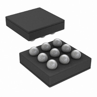
Mounting Type
Surface Mount
Package / Case
9-MicroSMD
For Use With
LM4673TMBD - BOARD EVALUATION LM4673TM
Lead Free Status / RoHS Status
Lead free / RoHS Compliant
Other names
LM4673TM
LM4673TMTR
LM4673TMTR


Application Information
GENERAL AMPLIFIER FUNCTION
The LM4673 features a filterless modulation scheme. The
differential outputs of the device switch at 300kHz from V
to GND. When there is no input signal applied, the two outputs
(V
in phase. Because the outputs of the LM4673 are differential,
the two signals cancel each other. This results in no net volt-
age across the speaker, thus there is no load current during
an idle state, conserving power.
With an input signal applied, the duty cycle (pulse width) of
the LM4673 outputs changes. For increasing output voltages,
the duty cycle of V
decreases. For decreasing output voltages, the converse oc-
curs, the duty cycle of V
V
yields the differential output voltage.
POWER DISSIPATION AND EFFICIENCY
In general terms, efficiency is considered to be the ratio of
useful work output divided by the total energy required to pro-
duce it with the difference being the power dissipated, typi-
cally, in the IC. The key here is “useful” work. For audio
systems, the energy delivered in the audible bands is con-
sidered useful including the distortion products of the input
signal. Sub-sonic (DC) and super-sonic components
(>22kHz) are not useful. The difference between the power
flowing from the power supply and the audio band power be-
ing transduced is dissipated in the LM4673 and in the trans-
ducer load. The amount of power dissipation in the LM4673
is very low. This is because the ON resistance of the switches
used to form the output waveforms is typically less than
0.25Ω. This leaves only the transducer load as a potential
"sink" for the small excess of input power over audio band
output power. The LM4673 dissipates only a fraction of the
excess power requiring no additional PCB area or copper
plane to act as a heat sink.
DIFFERENTIAL AMPLIFIER EXPLANATION
As logic supply voltages continue to shrink, designers are in-
creasingly turning to differential analog signal handling to
preserve signal to noise ratios with restricted voltage swing.
The LM4673 is a fully differential amplifier that features dif-
ferential input and output stages. A differential amplifier am-
plifies the difference between the two input signals. Tradition-
al audio power amplifiers have typically offered only single-
ended inputs resulting in a 6dB reduction in signal to noise
ratio relative to differential inputs. The LM4673 also offers the
possibility of DC input coupling which eliminates the two ex-
ternal AC coupling, DC blocking capacitors. The LM4673 can
be used, however, as a single ended input amplifier while still
retaining it's fully differential benefits. In fact, completely un-
related signals may be placed on the input pins. The LM4673
simply amplifies the difference between the signals. A major
benefit of a differential amplifier is the improved common
mode rejection ratio (CMRR) over single input amplifiers. The
common-mode rejection characteristic of the differential am-
plifier reduces sensitivity to ground offset related noise injec-
tion, especially important in high noise applications.
PCB LAYOUT CONSIDERATIONS
As output power increases, interconnect resistance (PCB
traces and wires) between the amplifier, load and power sup-
O
O
1 decreases. The difference between the two pulse widths
1 and V
O
2) switch with a 50% duty cycle, with both outputs
O
1 increases, while the duty cycle of V
O
2 increases while the duty cycle of
O
DD
2
11
ply create a voltage drop. The voltage loss on the traces
between the LM4673 and the load results is lower output
power and decreased efficiency. Higher trace resistance be-
tween the supply and the LM4673 has the same effect as a
poorly regulated supply, increased ripple on the supply line
also reducing the peak output power. The effects of residual
trace resistance increases as output current increases due to
higher output power, decreased load impedance or both. To
maintain the highest output voltage swing and corresponding
peak output power, the PCB traces that connect the output
pins to the load and the supply pins to the power supply
should be as wide as possible to minimize trace resistance.
The use of power and ground planes will give the best THD
+N performance. While reducing trace resistance, the use of
power planes also creates parasite capacitors that help to fil-
ter the power supply line.
The inductive nature of the transducer load can also result in
overshoot on one or both edges, clamped by the parasitic
diodes to GND and V
point, this is an aggressive waveform that can radiate or
conduct to other components in the system and cause inter-
ference. It is essential to keep the power and output traces
short and well shielded if possible. Use of ground planes,
beads, and micro-strip layout techniques are all useful in pre-
venting unwanted interference.
As the distance from the LM4673 and the speaker increase,
the amount of EMI radiation will increase since the output
wires or traces acting as antenna become more efficient with
length. What is acceptable EMI is highly application specific.
Ferrite chip inductors placed close to the LM4673 may be
needed to reduce EMI radiation. The value of the ferrite chip
is very application specific.
POWER SUPPLY BYPASSING
As with any power amplifier, proper supply bypassing is crit-
ical for low noise performance and high power supply rejec-
tion ratio (PSRR). The capacitor (C
close as possible to the LM4673. Typical applications employ
a voltage regulator with a 10µF and a 0.1µF bypass capacitors
that increase supply stability. These capacitors do not elimi-
nate the need for bypassing on the supply pin of the LM4673.
A 4.7µF tantalum capacitor is recommended.
SHUTDOWN FUNCTION
In order to reduce power consumption while not in use, the
LM4673 contains shutdown circuitry that reduces current
draw to less than 0.01µA. The trigger point for shutdown is
shown as a typical value in the Electrical Characteristics Ta-
bles and in the Shutdown Hysteresis Voltage graphs found in
the Typical Performance Characteristics section. It is best
to switch between ground and supply for minimum current
usage while in the shutdown state. While the LM4673 may be
disabled with shutdown voltages in between ground and sup-
ply, the idle current will be greater than the typical 0.01µA
value.
The LM4673 has an internal resistor connected between
GND and Shutdown pins. The purpose of this resistor is to
eliminate any unwanted state changes when the Shutdown
pin is floating. The LM4673 will enter the shutdown state when
the Shutdown pin is left floating or if not floating, when the
shutdown voltage has crossed the threshold. To minimize the
supply current while in the shutdown state, the Shutdown pin
should be driven to GND or left floating. If the Shutdown pin
is not driven to GND, the amount of additional resistor current
DD
in each case. From an EMI stand-
S
) location should be as
www.national.com
Related parts for LM4673TM/NOPB
Image
Part Number
Description
Manufacturer
Datasheet
Request
R

Part Number:
Description:
AUDIO AMP, MONO CLASS D, POWERWISE
Manufacturer:
National Semiconductor
Datasheet:

Part Number:
Description:
National Semiconductor [8-Bit D/A Converter]
Manufacturer:
National Semiconductor
Datasheet:
Part Number:
Description:
National Semiconductor [Media Coprocessor]
Manufacturer:
National Semiconductor
Datasheet:
Part Number:
Description:
Digitally Controlled Tone and Volume Circuit with Stereo Audio Power Amplifier, Microphone Preamp Stage and National 3D Sound
Manufacturer:
National Semiconductor
Datasheet:
Part Number:
Description:
Digitally Controlled Tone and Volume Circuit with Stereo Audio Power Amplifier, Microphone Preamp Stage and National 3D Sound
Manufacturer:
National Semiconductor
Datasheet:
Part Number:
Description:
AC97 Rev 2 Codec with Sample Rate Conversion and National 3D Sound
Manufacturer:
National Semiconductor
Part Number:
Description:
Manufacturer:
National Semiconductor
Datasheet:
Part Number:
Description:
Manufacturer:
National Semiconductor
Datasheet:
Part Number:
Description:
General Purpose, Low Voltage, Low Power, Rail-to-Rail Output Operational Amplifiers
Manufacturer:
National Semiconductor
Datasheet:
Part Number:
Description:
8-bit 20 MSPS flash A/D converter.
Manufacturer:
National Semiconductor
Datasheet:
Part Number:
Description:
Low Noise Quad Operational Amplifier
Manufacturer:
National Semiconductor
Datasheet:
Part Number:
Description:
Quad Differential Line Receivers
Manufacturer:
National Semiconductor
Datasheet:
Part Number:
Description:
Quad High Speed Trapezoidal? Bus Transceiver
Manufacturer:
National Semiconductor
Datasheet:
Part Number:
Description:
Dual Line Receiver
Manufacturer:
National Semiconductor
Datasheet: