XPSAC3421P Crouzet USA, XPSAC3421P Datasheet - Page 185
XPSAC3421P
Manufacturer Part Number
XPSAC3421P
Description
89H6658
Manufacturer
Crouzet USA
Datasheet
1.XPSMCCPC.pdf
(274 pages)
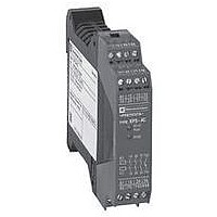
Specifications of XPSAC3421P
Contact Current Max
60mA
Contact Voltage Ac Nom
115V
Contact Configuration
3PST-NO
Relay Mounting
DIN Rail
External Height
66mm
External Width
114mm
External Depth
22.5mm
Rohs Compliant
Yes


10
10
1
1
2
2
3
3
4
4
5
5
6
6
7
7
8
8
9
9
Wiring diagrams
S1: Emergency stop button with 2 N.C. contacts (recommended application).
S2: Start button.
ESC: External start conditions.
Y1 (S33) - Y2: Feedback loop.
F1: 4 A max.
(1) With start button monitoring.
(2) Without start button monitoring.
(3) The outputs must be fuse protected. Technical characteristics for maximum rating of fuses, see page 4.
(4) a 115/230 V only.
(5) For automatic start, jumper S2 (N.O. start button between terminals S33-Y1). This is only feasible when configured without start button monitoring (Y3 and Y4
With
Start button
Without
Start button
Outputs
1 With start button monitoring (Y3-Y5 connection).
2 Without start button monitoring (Y3-Y4 connection).
3 Without start button (connection Y3-Y4 and S33-Y1).
Tv: adjustable time.
1
2
3
4
Principle:
page 2/178
2/184
XPSATE
Module XPSATE associated with an Emergency stop button
Functional diagram of module XPSATE with Emergency stop button monitoring
Description of LEDs
jumpered). If S2 is jumpered and the module is configured for start button monitoring (Y3 and Y5 jumpered), the N.O. safety contacts will not close.
Key
Emergency stop (O1)
Solid-state output Y89 (S12)
Emergency stop (O2)
Solid-state output Y90 (S22)
Start button
Start button
Emergency stop (O2 or O1)
Solid-state output Y89 (S12)
Emergency stop (O2 or O1)
Solid-state output Y90 (S22)
Start button
External start
conditions
Output 13-14 (N.O.)
Output 23-24 (N.O.)
Output 57-58 (N.O.)
Output 67-68 (N.O.)
Output 77-78 (N.O.)
Solid-state output Y88 (A1/A2)
Solid-state output Y91 (Stop 1)
0
Start
1
Characteristics:
page 2/178
voltage
Supply
(continued)
Begin
Tmax. = 75 ms
Logic
Emergency stop
not activated
Safety automation system solutions
Preventa™ safety relay modules type XPSATE
For Emergency stop and switch monitoring
References:
page 2/180
1 Supply voltage A1-A2, internal electronic fuse status.
2 S12 (A) input status.
3 S22 (B) input status.
4 Stop category 1 outputs closed.
opening safety
Instantaneous
2
3
1
category 0
outputs
Stop
safety outputs
category 1
Time delay
Tv = 0…30 s
opening
Stop
Emergency stop
activated
Wiring Diagrams:
page 2/181
To PLC
Dimensions:
page 2/260
Related parts for XPSAC3421P
Image
Part Number
Description
Manufacturer
Datasheet
Request
R

Part Number:
Description:
SCREW SOCKET (OT08PC)
Manufacturer:
Crouzet USA
Datasheet:

Part Number:
Description:
PANEL PLATE FOR 813
Manufacturer:
Crouzet USA
Datasheet:
Part Number:
Description:
Controller; CTD46 Dual Display Temperature, 1/16 DIN, NEMA 4X, 110/220VAC
Manufacturer:
Crouzet USA
Datasheet:

Part Number:
Description:
11R1084
Manufacturer:
Crouzet USA
Datasheet:
Part Number:
Description:
11R1086
Manufacturer:
Crouzet USA
Datasheet:
Part Number:
Description:
11R1087
Manufacturer:
Crouzet USA
Datasheet:
Part Number:
Description:
11R1089
Manufacturer:
Crouzet USA
Datasheet:
Part Number:
Description:
11R1078
Manufacturer:
Crouzet USA
Datasheet:
Part Number:
Description:
11R1079
Manufacturer:
Crouzet USA
Datasheet: