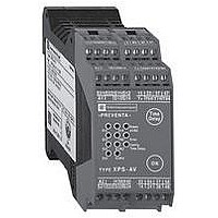
XPSAV11113P Crouzet USA, XPSAV11113P Datasheet - Page 145

XPSAV11113P
Manufacturer Part Number
XPSAV11113P
Description
89H6663
Manufacturer
Crouzet USA
Datasheet
1.XPSMCCPC.pdf
(274 pages)
Specifications of XPSAV11113P
Contact Voltage Dc Nom
24V
Relay Mounting
DIN Rail
External Height
66mm
External Width
114mm
External Depth
45mm
Rohs Compliant
Yes
- Current page: 145 of 274
- Download datasheet (15Mb)
10
10
1
1
2
2
3
3
4
4
5
5
6
6
7
7
8
8
9
9
Wiring diagrams
+
0 V
The zero speed signal (validation of the output) will be activated only if:
1: one input is in a high state,
2: the other input is in a low state,
3: the frequency of the two inputs is less than the stated value.
(1) Technical characteristics for maximum rating of fuses, see page 2/122.
(2) Only applicable to XPSMC32Zp.
(3) Only one “Zero speed detection” function can be connected to an XPSMC controller, and only to the inputs i1 and i2.
Sensor control
Presentation:
page 2/118
2/144
Zero speed detection
Category 4 conforming to standard EN 954-1.
Wiring diagram
Functional diagram
24 V
230 V
(1)
F1
A1
A2
C8 C7 C6 C5 C4 C3 C2 C1
T
24 V
Sensor B1
Sensor B2
5 V
Characteristics:
page 2/122
Logic
GND
(continued)
GND
µC 1
µC 2
B2
B1
GND
+
–
A
+
–
A
I1
(3)
K0
Chnl. 1
Chnl. 2
I2
K01
I3
Channel 1
O1
Safety automation system solutions
Preventa™ configurable safety controllers
Type XPSMC
References:
page 2/124
… I16
Chnl. 1
Chnl. 2
K02
XPS MC
Channel 2
O2
Chnl. 1
Chnl. 2
Input 1 (I1)
Sensor B1
Input 2 (I2)
Sensor B2
Output
O3
Chnl. 1
Chnl. 2
Sub-D 9
I17
Zero speed
f1, f2 < f max.
Dimensions:
page 2/125
(2)
O4
…
Chnl. 1
Chnl. 2
Control
outputs
I32
Ter
O5
Chnl. 1
Chnl. 2
Rotation
f1, f2 > f max.
O6
K1
K2
Wiring Diagrams:
page 2/126
13
14
23
24
Zero speed
f1, f2 < f max.
K3
K4
H1
34
33
+
230 V
43
24 V
44
0 V
Related parts for XPSAV11113P
Image
Part Number
Description
Manufacturer
Datasheet
Request
R

Part Number:
Description:
SCREW SOCKET (OT08PC)
Manufacturer:
Crouzet USA
Datasheet:

Part Number:
Description:
PANEL PLATE FOR 813
Manufacturer:
Crouzet USA
Datasheet:

Part Number:
Description:
Controller; CTD46 Dual Display Temperature, 1/16 DIN, NEMA 4X, 110/220VAC
Manufacturer:
Crouzet USA
Datasheet:

Part Number:
Description:
11R1084
Manufacturer:
Crouzet USA
Datasheet:

Part Number:
Description:
11R1086
Manufacturer:
Crouzet USA
Datasheet:

Part Number:
Description:
11R1087
Manufacturer:
Crouzet USA
Datasheet:

Part Number:
Description:
11R1089
Manufacturer:
Crouzet USA
Datasheet:

Part Number:
Description:
11R1078
Manufacturer:
Crouzet USA
Datasheet:

Part Number:
Description:
11R1079
Manufacturer:
Crouzet USA
Datasheet:


