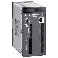
XPSMC16Z Crouzet USA, XPSMC16Z Datasheet - Page 154

XPSMC16Z
Manufacturer Part Number
XPSMC16Z
Description
34M0430
Manufacturer
Crouzet USA
Datasheet
1.XPSMCCPC.pdf
(274 pages)
Specifications of XPSMC16Z
No. Of Digital Inputs
16
No. Of Digital Outputs
10
Rohs Compliant
Yes
- Current page: 154 of 274
- Download datasheet (15Mb)
Wiring diagrams
0 V
(1) Technical characteristics for maximum rating of fuses, see page 2/122.
(2) Only applicable to XPSMC32Zp.
t Z = enabling time
a
+
Input
Closing enabling switch 1-2
Input
Opening enabling switch 5-6
Input
Closing enabling switch 3-4
Output
Key
Enabling switch monitoring, 3 contact type
Category 4 conforming to standard EN 954-1.
Wiring diagram
Functional diagram
24 V
230 V
(1)
F1
0
A1
A2
C8 C7 C6 C5 C4 C3 C2 C1
T
1
24 V
5 V
Start-up
Logic
GND
(continued)
Enabling switch
Position 1
GND
µC 1
µC 2
Validation
GND
S4
0
1 2
NO
K0
Chnl. 1
Chnl. 2
I1
Enabling switch
K01
NC
Position 0
Channel 1
I2
O1
Safety automation system solutions
Preventa™ configurable safety controllers
Type XPSMC
NO
I3
Chnl. 1
Chnl. 2
K02
I4
XPS MC
Channel 2
O2
Chnl. 1
Chnl. 2
Enabling switch
I5
Position 1
t < tZ
O3
Chnl. 1
Chnl. 2
I6
Sub-D 9
I7
O4
Chnl. 1
Chnl. 2
Enabling switch
I8
Position 2
I9
Ter
O5
… I16
Chnl. 1
Chnl. 2
Control
outputs
O6
I17
Enabling switch
(2)
…
Position 1
I32
K1
K2
NO
NO
NO
NO
NC
NC
1-2
5-6
3-4
1-2
5-6
3-4
Key
Activated
Switching of 3 contact
enabling switch:
13
14
0
0
Enabling switch
23
24
Position 0
K3
K4
Deactivated
H1
1
1
a
33
34
2/153
+
230 V
24 V
43
44
0 V
2
2
10
10
1
1
2
2
3
3
4
4
5
5
6
6
7
7
8
8
9
9
Related parts for XPSMC16Z
Image
Part Number
Description
Manufacturer
Datasheet
Request
R

Part Number:
Description:
SCREW SOCKET (OT08PC)
Manufacturer:
Crouzet USA
Datasheet:

Part Number:
Description:
PANEL PLATE FOR 813
Manufacturer:
Crouzet USA
Datasheet:

Part Number:
Description:
Controller; CTD46 Dual Display Temperature, 1/16 DIN, NEMA 4X, 110/220VAC
Manufacturer:
Crouzet USA
Datasheet:

Part Number:
Description:
11R1084
Manufacturer:
Crouzet USA
Datasheet:

Part Number:
Description:
11R1086
Manufacturer:
Crouzet USA
Datasheet:

Part Number:
Description:
11R1087
Manufacturer:
Crouzet USA
Datasheet:

Part Number:
Description:
11R1089
Manufacturer:
Crouzet USA
Datasheet:

Part Number:
Description:
11R1078
Manufacturer:
Crouzet USA
Datasheet:

Part Number:
Description:
11R1079
Manufacturer:
Crouzet USA
Datasheet:


