XPSMC32ZC Crouzet USA, XPSMC32ZC Datasheet - Page 234
XPSMC32ZC
Manufacturer Part Number
XPSMC32ZC
Description
34M0434
Manufacturer
Crouzet USA
Datasheet
1.XPSMCCPC.pdf
(274 pages)
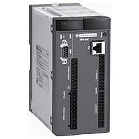
Specifications of XPSMC32ZC
No. Of Digital Inputs
32
No. Of Digital Outputs
10
Rohs Compliant
Yes


Wiring diagrams
Contacts 95/96 and 97/98 are trip contacts for an overload relay.
S1 is one of the N.C. safety contacts in an XCSE switch
Y1 is the N.C. solenoid contact in the XCSE switch (wired in series with the S1)
(1) Control signal.
(2) Relay hard contact outputs with pulse time delay.
ESC: External start conditions.
LED details: see page 2/232.
Principle:
page 2/230
L1
L2
L3
FM2
PE
L1 (
XPSTSW
Guard unlocking application using zero speed detection
Wiring diagram
FM1
(1)
4
+
)
F1
3
A1
A2
M
KM1
XPS TSW
T
PE
L1
L2
L3
F0
PE
L1 (
+
Logic
Y53
)
A1 Z1 Z2 Z3
A2
Characteristics:
page 2/230
K1/K2
Y1
XPS VN
(continued)
Y54
To PLC
1
F OK
Y64
2
Y2
Y1
ESC
13
14
K1
K2
KM1
S2
S3
FM2
S1
Y1
21
22
A1/A2
17
18
Safety automation system solutions
Preventa™ safety relay modules type XPSTSW
For safety time delays
Y34
References:
page 2/231
S4
(2)
25
26
Y33/Y43
KM1
Y44
L1 (
35
36
+
)
S2 is the motor stop push button
S3 is the motor start push button, in parallel of KM1 contact
S4 is the push button to energize the XCSE solenoid to unlock the guard
Input A1-A2
Input Y1-Y2
Output 17-18 (N.O.)
Output 25-26 (N.C.)
Signalling
output
Y53-Y54
Key
te: power-up time
tw: pulse time
Signalling
output
Y53-Y64
Output 35-36 (N.C.)
Functional diagram of module XPSTSW
Guard closed
A1
A2
0
XPS TSW
T
PE
Wiring Diagrams:
page 2/231
1
Supply
voltage
activated
+
tw
Y53
K1/K2
Y1
Supply
voltage
deactivated
Y54
To PLC
1
F OK
KM1
Y64
2
Y2
Supply
voltage
activated
No starting,
Y1-Y2 open
Dimensions:
page 2/260
K1
K2
Supply
voltage
deactivated
17
18
S4
25
26
te
tw
35
36
L1 (
2/233
+
)
0
10
1
2
3
4
5
6
7
8
9
Related parts for XPSMC32ZC
Image
Part Number
Description
Manufacturer
Datasheet
Request
R

Part Number:
Description:
SCREW SOCKET (OT08PC)
Manufacturer:
Crouzet USA
Datasheet:

Part Number:
Description:
PANEL PLATE FOR 813
Manufacturer:
Crouzet USA
Datasheet:
Part Number:
Description:
Controller; CTD46 Dual Display Temperature, 1/16 DIN, NEMA 4X, 110/220VAC
Manufacturer:
Crouzet USA
Datasheet:

Part Number:
Description:
11R1084
Manufacturer:
Crouzet USA
Datasheet:
Part Number:
Description:
11R1086
Manufacturer:
Crouzet USA
Datasheet:
Part Number:
Description:
11R1087
Manufacturer:
Crouzet USA
Datasheet:
Part Number:
Description:
11R1089
Manufacturer:
Crouzet USA
Datasheet:
Part Number:
Description:
11R1078
Manufacturer:
Crouzet USA
Datasheet:
Part Number:
Description:
11R1079
Manufacturer:
Crouzet USA
Datasheet: