XPSMC32ZP Crouzet USA, XPSMC32ZP Datasheet - Page 155
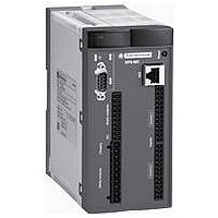
XPSMC32ZP
Manufacturer Part Number
XPSMC32ZP
Description
34M0435
Manufacturer
Crouzet USA
Datasheet
1.XPSMCCPC.pdf
(274 pages)
Specifications of XPSMC32ZP
No. Of Digital Inputs
32
No. Of Digital Outputs
10
Rohs Compliant
Yes


10
10
1
1
2
2
3
3
4
4
5
5
6
6
7
7
8
8
9
9
Wiring diagrams
a
+
0 V
S8: Operating modes:
0 - stop,
1 - adjust,
2 - jog.
(1) Technical characteristics for maximum rating of fuses, see page 2/122.
(2) Only applicable to XPSMC32Zp (I17…I32).
(1) Not used.
Presentation:
page 2/118
Emergency stop
Adjust mode
Jog mode
Automatic mode
Hydraulic pump (1)
Opening command
Closing command (1)
Safety device
OT
NWK (1)
UT
Closing valve (1)
Opening valve (1)
Closing + Opening valve (1)
Output - opening
Output - closing
Overtravel OK
N
2/154
Hydraulic press
Category 4 conforming to standard EN 954-1.
Wiring diagram
Functional diagram
Hydraulic press, adjust mode
24 V
230 V
(1)
F1
A1
A2
C8
T
C7 C6 C5 C4 C3 C2 C1
24 V
5 V
Logic
AUF = open, to be used in inching.
OT = Limit switch associated with top dead center (TDC).
UT = Limit switch associated with bottom dead center (BDC).
NWK = overtravel monitoring.
Characteristics:
page 2/122
GND
Key
(continued)
GND
µC 1
µC 2
0
B3
B2
B1
GND
A
A
A
(2)
+
–
+
–
+
–
I1
1
I17
command
K0
Chnl. 1
Chnl. 2
I2
Closing
I18
Y1
I3
O1
I19
S1
Closing
I4
Safety automation system solutions
Preventa™ configurable safety controllers
Type XPSMC
References:
page 2/124
AUF
Chnl. 1
Chnl. 2
S9
S2
I20
I5
Opening
command
OT
XPS MC
Y2
S3
I21
O2
I6
UT
Opening
S4
I22
Chnl. 1
Chnl. 2
I7
NWK
I23
S5
Y3
I8
O3
I24
Closing
+
Opening
Sub-D 9
I9
Emer.
stop
KM1
Kx
Chnl. 1
Chnl. 2
S3
I25
I10
Dimensions:
page 2/125
I26
Ter
I11
O4
Chnl. 1
Chnl. 2
S4
2H
I27
H1
I12
I28
Overtravel
OK
O5
X1
X2
I13
Chnl. 1
Chnl. 2
S5
2H
I29
I14
I30
O6
I15
I31
K1
K2
I16
Wiring Diagrams:
page 2/126
S8
KM1
I32
0
13
14 24
1 2
OFF-Stop
ON-Run
23
K3
K4
FM1
SM1
SM2
H1
a
34 44
33 43
(1)
F2
+
KM1
230 V
24 V
0 V
N
Related parts for XPSMC32ZP
Image
Part Number
Description
Manufacturer
Datasheet
Request
R

Part Number:
Description:
SCREW SOCKET (OT08PC)
Manufacturer:
Crouzet USA
Datasheet:

Part Number:
Description:
PANEL PLATE FOR 813
Manufacturer:
Crouzet USA
Datasheet:
Part Number:
Description:
Controller; CTD46 Dual Display Temperature, 1/16 DIN, NEMA 4X, 110/220VAC
Manufacturer:
Crouzet USA
Datasheet:

Part Number:
Description:
11R1084
Manufacturer:
Crouzet USA
Datasheet:
Part Number:
Description:
11R1086
Manufacturer:
Crouzet USA
Datasheet:
Part Number:
Description:
11R1087
Manufacturer:
Crouzet USA
Datasheet:
Part Number:
Description:
11R1089
Manufacturer:
Crouzet USA
Datasheet:
Part Number:
Description:
11R1078
Manufacturer:
Crouzet USA
Datasheet:
Part Number:
Description:
11R1079
Manufacturer:
Crouzet USA
Datasheet: