TDA8932BTW/N2,112 NXP Semiconductors, TDA8932BTW/N2,112 Datasheet - Page 6
TDA8932BTW/N2,112
Manufacturer Part Number
TDA8932BTW/N2,112
Description
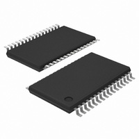
IC AMP AUDIO 55W STER D 32TSSOP
Manufacturer
NXP Semiconductors
Type
Class Dr
Datasheet
1.TDA8932BTWN2118.pdf
(48 pages)
Specifications of TDA8932BTW/N2,112
Package / Case
32-TSSOP Exposed Pad, 32-eTSSOP, 32-HTSSOP
Output Type
1-Channel (Mono) or 2-Channel (Stereo)
Max Output Power X Channels @ Load
55W x 1 @ 8 Ohm; 26.5W x 2 @ 4 Ohm
Voltage - Supply
10 V ~ 36 V, ±5 V ~ 18 V
Features
Depop, Differential Inputs, Mute, Short-Circuit and Thermal Protection
Mounting Type
Surface Mount
Mounting Style
SMD/SMT
Lead Free Status / RoHS Status
Lead free / RoHS Compliant
Other names
935283479112
TDA8932BTW
TDA8932BTW
TDA8932BTW/N2
TDA8932BTW/N2
TDA8932BTW
TDA8932BTW
TDA8932BTW/N2
TDA8932BTW/N2


NXP Semiconductors
TDA8932B_4
Product data sheet
8.2 Mode selection and interfacing
The TDA8932B supports four operating modes, selected using pins POWERUP and
ENGAGE:
Pins POWERUP and ENGAGE are referenced to pin CGND.
Table 4
ENGAGE pins.
Table 4.
[1]
If the transition between Mute mode and Operating mode is controlled via a time constant,
the start-up will be pop free since the DC output offset voltage is applied gradually to the
output between Mute mode and Operating mode. The bias current setting of the
VI-converters is related to the voltage on pin ENGAGE:
The time constant required to apply the DC output offset voltage gradually between Mute
mode and Operating mode can be generated by connecting a 470 nF decoupling
capacitor to pin ENGAGE.
Mode
Sleep
Mute
Operating
Fault
•
•
•
•
•
•
Sleep mode: with low supply current.
Mute mode: the amplifiers are switching idle (50 % duty cycle), but the audio signal at
the output is suppressed by disabling the Vl-converter input stages. The capacitors on
pins HVP1 and HVP2 have been charged to half the supply voltage (asymmetrical
supply only).
Operating mode: the amplifiers are fully operational with output signal.
Fault mode.
In case of symmetrical supply conditions the voltage applied to pins POWERUP and ENGAGE must never
exceed the supply voltage (V
Mute mode: the bias current setting of the VI-converters is zero (VI-converters
disabled)
Operating mode: the bias current is at maximum
shows the different modes as a function of the voltages on the POWERUP and
Mode selection
Pin
POWERUP
< 0.8 V
2 V to 6.0 V
2 V to 6.0 V
2 V to 6.0 V
Rev. 04 — 18 December 2008
[1]
[1]
[1]
DDA
, V
DDP1
or V
ENGAGE
< 0.8 V
< 0.8 V
2.4 V to 6.0 V
don’t care
DDP2
).
[1]
[1]
Class-D audio amplifier
DIAG
don’t care
> 2 V
> 2 V
< 0.8 V
TDA8932B
© NXP B.V. 2008. All rights reserved.
6 of 48
Related parts for TDA8932BTW/N2,112
Image
Part Number
Description
Manufacturer
Datasheet
Request
R

Part Number:
Description:
Audio Amplifiers 2X15W BTL CLASS D AMP+VOLCTRL
Manufacturer:
NXP Semiconductors

Part Number:
Description:
Audio Amplifiers 2X15W BTL CLASS D AMP+VOLCTRL
Manufacturer:
NXP Semiconductors
Datasheet:

Part Number:
Description:
IC AMP AUDIO 55W STER D 32TSSOP
Manufacturer:
NXP Semiconductors
Datasheet:
Part Number:
Description:
Audio Amplifiers 2X15W BTL CLASS D
Manufacturer:
NXP Semiconductors
Part Number:
Description:
IC AMP AUDIO CLASS D 32HTSSOP
Manufacturer:
NXP Semiconductors
Datasheet:
Part Number:
Description:
Tda8932b Class-d Audio Amplifier
Manufacturer:
NXP Semiconductors
Datasheet:

Part Number:
Description:
IC AMP AUDIO 55W STER D 32SOIC
Manufacturer:
NXP Semiconductors
Datasheet:
Part Number:
Description:
Audio Amplifiers 2X15W BTL CLASS D AMP+VOLCTRL
Manufacturer:
NXP Semiconductors
Part Number:
Description:
Audio Amplifiers 2X15W BTL CLASS D AMP+VOLCTRL
Manufacturer:
NXP Semiconductors
Part Number:
Description:
IC AMP AUDIO 55W STER D 32SOIC
Manufacturer:
NXP Semiconductors
Datasheet:
Part Number:
Description:
Manufacturer:
NXP Semiconductors
Datasheet:
Part Number:
Description:
Tda8932 Class-d Audio Amplifier
Manufacturer:
NXP Semiconductors
Datasheet:
Part Number:
Description:
NXP Semiconductors designed the LPC2420/2460 microcontroller around a 16-bit/32-bitARM7TDMI-S CPU core with real-time debug interfaces that include both JTAG andembedded trace
Manufacturer:
NXP Semiconductors
Datasheet:

Part Number:
Description:
NXP Semiconductors designed the LPC2458 microcontroller around a 16-bit/32-bitARM7TDMI-S CPU core with real-time debug interfaces that include both JTAG andembedded trace
Manufacturer:
NXP Semiconductors
Datasheet:
Part Number:
Description:
NXP Semiconductors designed the LPC2468 microcontroller around a 16-bit/32-bitARM7TDMI-S CPU core with real-time debug interfaces that include both JTAG andembedded trace
Manufacturer:
NXP Semiconductors
Datasheet: