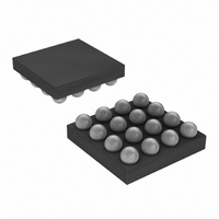
MAX4410EBE+T Maxim Integrated Products, MAX4410EBE+T Datasheet - Page 13

MAX4410EBE+T
Manufacturer Part Number
MAX4410EBE+T
Description
IC AMP AUDIO .08W STER AB 16UCSP
Manufacturer
Maxim Integrated Products
Series
DirectDrive™r
Type
Class ABr
Datasheet
1.MAX4410EBET.pdf
(20 pages)
Specifications of MAX4410EBE+T
Output Type
Headphones, 2-Channel (Stereo)
Max Output Power X Channels @ Load
80mW x 2 @ 16 Ohm
Voltage - Supply
1.8 V ~ 3.6 V
Features
Depop, Short-Circuit and Thermal Protection, Shutdown
Mounting Type
Surface Mount
Package / Case
16-UCSP®
Lead Free Status / RoHS Status
Lead free / RoHS Compliant
4) When using the headphone jack as a line out to other
In addition to the cost and size disadvantages of the DC-
blocking capacitors required by conventional head-
phone amplifiers, these capacitors limit the amplifier’s
low-frequency response and can distort the audio signal.
1) The impedance of the headphone load and the DC-
2) The voltage coefficient of the DC-blocking capacitor
The combination of low-frequency attenuation and fre-
quency-dependent distortion compromises audio
reproduction in portable audio equipment that empha-
sizes low-frequency effects such as multimedia lap-
tops, as well as MP3, CD, and DVD players. By
eliminating the DC-blocking capacitors through
DirectDrive technology, these capacitor-related defi-
ciencies are eliminated.
blocking capacitor form a highpass filter with the
-3dB point set by:
where R
the DC-blocking capacitor value. The highpass filter
is required by conventional single-ended, single
power-supply headphone drivers to block the midrail
DC bias component of the audio signal from the
headphones. The drawback to the filter is that it can
attenuate low-frequency signals. Larger values of
C
er, more expensive capacitors. Figure 2 shows the
relationship between the size of C
ing low-frequency attenuation. Note that the -3dB
point for a 16Ω headphone with a 100µF blocking
capacitor is 100Hz, well within the normal audio
band, resulting in low-frequency attenuation of the
reproduced signal.
contributes distortion to the reproduced audio signal
as the capacitance value varies as a function of the
voltage change across the capacitor. At low fre-
quencies, the reactance of the capacitor dominates
at frequencies below the -3dB point and the voltage
coefficient appears as frequency-dependent distor-
tion. Figure 3 shows the THD + N introduced by two
different capacitor dielectric types. Note that below
100Hz, THD + N increases rapidly.
equipment, the bias voltage on the sleeve may con-
flict with the ground potential from other equipment,
resulting in possible damage to the drivers.
OUT
80mW, DirectDrive Stereo Headphone Driver
reduce this effect but result in physically larg-
L
is the headphone impedance and C
f
______________________________________________________________________________________
−
3
dB
=
2π
Low-Frequency Response
R C
L OUT
1
OUT
and the result-
OUT
is
The MAX4410 features a low-noise charge pump. The
320kHz switching frequency is well beyond the audio
range, and thus does not interfere with the audio sig-
nals. The switch drivers feature a controlled switching
speed that minimizes noise generated by turn-on and
turn-off transients. By limiting the switching speed of the
switches, the di/dt noise caused by the parasitic bond
wire and trace inductance is minimized. Although not
typically required, additional high-frequency noise atten-
uation can be achieved by increasing the size of C2
(see Typical Application Circuit).
Figure 2. Low-Frequency Attenuation for Common DC-Blocking
Capacitor Values
Figure 3. Distortion Contributed by DC-Blocking Capacitors
0.0001
0.001
0.01
-10
-15
-20
-25
-30
-35
0.1
10
-3
-5
1
0
10
10
330µF
TO DC-BLOCKING CAPACITORS
ALUM/ELEC
with Shutdown
ADDITIONAL THD + N DUE
LF ROLL OFF (16Ω LOAD)
220µF
100
100µF
FREQUENCY (Hz)
33µF
FREQUENCY (Hz)
TANTALUM
100
1k
-3dB CORNER FOR
100µF IS 100Hz
10k
Charge Pump
100k
1k
13


