TDA7297D STMicroelectronics, TDA7297D Datasheet - Page 3
TDA7297D
Manufacturer Part Number
TDA7297D
Description
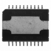
IC AMP AUDIO 10W STER POWERSO20
Manufacturer
STMicroelectronics
Type
Class ABr
Datasheet
1.TDA7297D13TR.pdf
(11 pages)
Specifications of TDA7297D
Output Type
2-Channel (Stereo)
Max Output Power X Channels @ Load
10W x 2 @ 8 Ohm
Voltage - Supply
6.5 V ~ 18 V
Features
Mute, Short-Circuit and Thermal Protection, Standby
Mounting Type
Surface Mount
Package / Case
PowerSO-20 Exposed Bottom Pad
Operational Class
Class-AB
Audio Amplifier Output Configuration
2-Channel Stereo
Output Power (typ)
10x2@8OhmW
Audio Amplifier Function
Speaker
Total Harmonic Distortion
0.1@8Ohm@1W%
Single Supply Voltage (typ)
9/12/15V
Dual Supply Voltage (typ)
Not RequiredV
Power Supply Requirement
Single
Power Dissipation
33W
Rail/rail I/o Type
No
Power Supply Rejection Ratio
56dB
Single Supply Voltage (min)
6.5V
Single Supply Voltage (max)
18V
Dual Supply Voltage (min)
Not RequiredV
Dual Supply Voltage (max)
Not RequiredV
Operating Temp Range
0C to 70C
Operating Temperature Classification
Commercial
Mounting
Surface Mount
Pin Count
20
Package Type
Power SO20
Lead Free Status / RoHS Status
Contains lead / RoHS non-compliant
Other names
497-3968-5
Available stocks
Company
Part Number
Manufacturer
Quantity
Price

Part Number:
TDA7297D
Manufacturer:
ST
Quantity:
20 000
Part Number:
TDA7297D13TR
Manufacturer:
ST
Quantity:
20 000


Table 4. Electrical Characteristcs (V
specified)
3
STAND-BY AND MUTE FUNCTIONS
3.1 Microprocessor Application
In order to avoid annoying "Pop-Noise" during Turn-On/Off transients, it is necessary to guarantee the right St-
by and mute signals sequence.It is quite simple to obtain this function using a microprocessor (Fig. 4 and 5).
At first St-by signal (from P) goes high and the voltage across the St-by terminal (Pin 9) starts to increase ex-
ponentially. The external RC network is intended to turn-on slowly the biasing circuits of the amplifier, this to
avoid "POP" and "CLICK" on the outputs.
When this voltage reaches the St-by threshold level, the amplifier is switched-on and the external capacitors in
series to the input terminals (C1, C3) start to charge.
It's necessary to mantain the mute signal low until the capacitors are fully charged, this to avoid that the device
goes in play mode causing a loud "Pop Noise" on the speakers.
A delay of 100-200ms between St-by and mute signals is suitable for a proper operation.
Symbol
VT
VT
A
I
THD
SVR
ST-BY
V
V
MUTE
CT
P
G
T
e
MUTE
ST-BY
R
I
G
CC
OS
q
w
N
APPLICATIVE SUGGESTIONS
O
V
i
V
Supply Range
Total Quiescent Current
Output Offset Voltage
Output Power
Total Harmonic Distortion
Supply Voltage Rejection
Crosstalk
Mute Attenuation
Thermal Threshold
Closed Loop Voltage Gain
Voltage Gain Matching
Input Resistance
Mute Threshold
St-by Threshold
St-by Current
Total Output Noise Voltage
Parameter
CC
R
THD 10%
P
P
f = 100Hz to 15KHz
f = 100Hz, VR =0.5V
Vo = -30dB
A Curve
f = 20Hz to 20KHz
= 13V, R
O
O
L
=
= 1W
= 0.1W to 5W
Test Condition
L
= 8 , f = 1KHz, T
amb
Min.
6.5
8.3
2.3
0.8
40
46
60
31
25
= 25°C unless otherwise
Typ.
150
150
220
0.1
2.9
1.3
50
10
56
60
80
32
30
Max.
120
100
500
0.3
0.5
4.1
1.8
18
65
33
TDA7297D
1
Unit
mA
mV
K
dB
dB
dB
°C
dB
dB
W
%
%
V
V
V
A
V
V
3/11
Related parts for TDA7297D
Image
Part Number
Description
Manufacturer
Datasheet
Request
R

Part Number:
Description:
STMicroelectronics [RIPPLE-CARRY BINARY COUNTER/DIVIDERS]
Manufacturer:
STMicroelectronics
Datasheet:
Part Number:
Description:
STMicroelectronics [LIQUID-CRYSTAL DISPLAY DRIVERS]
Manufacturer:
STMicroelectronics
Datasheet:

Part Number:
Description:
BOARD EVAL FOR MEMS SENSORS
Manufacturer:
STMicroelectronics
Datasheet:
Part Number:
Description:
NPN TRANSISTOR POWER MODULE
Manufacturer:
STMicroelectronics
Datasheet:
Part Number:
Description:
TURBOSWITCH ULTRA-FAST HIGH VOLTAGE DIODE
Manufacturer:
STMicroelectronics
Datasheet:
Part Number:
Description:
Manufacturer:
STMicroelectronics
Datasheet:
Part Number:
Description:
DIODE / SCR MODULE
Manufacturer:
STMicroelectronics
Datasheet:
Part Number:
Description:
DIODE / SCR MODULE
Manufacturer:
STMicroelectronics
Datasheet:
Part Number:
Description:
Search -----> STE16N100
Manufacturer:
STMicroelectronics
Datasheet:
Part Number:
Description:
Search ---> STE53NA50
Manufacturer:
STMicroelectronics
Datasheet:
Part Number:
Description:
NPN Transistor Power Module
Manufacturer:
STMicroelectronics
Datasheet:
Part Number:
Description:
DIODE / SCR MODULE
Manufacturer:
STMicroelectronics
Datasheet: