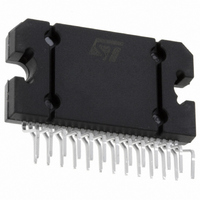
TDA7382 STMicroelectronics, TDA7382 Datasheet - Page 8

TDA7382
Manufacturer Part Number
TDA7382
Description
IC AMP AUDIO PWR 30W 25FLEXIWATT
Manufacturer
STMicroelectronics
Type
Class ABr
Datasheet
1.TDA7382.pdf
(10 pages)
Specifications of TDA7382
Output Type
4-Channel (Quad)
Max Output Power X Channels @ Load
30W x 4 @ 4 Ohm
Voltage - Supply
8 V ~ 18 V
Features
Mute, Short-Circuit and Thermal Protection, Standby
Mounting Type
Through Hole
Package / Case
25-Flexiwatt (bent and staggered leads)
Operational Class
Class-AB
Audio Amplifier Output Configuration
4-Channel Stereo
Audio Amplifier Function
Speaker
Total Harmonic Distortion
0.04@4Ohm@4W%
Dual Supply Voltage (typ)
Not RequiredV
Power Supply Requirement
Single
Power Dissipation
80W
Rail/rail I/o Type
Rail to Rail Output
Power Supply Rejection Ratio
65dB
Single Supply Voltage (max)
18V
Dual Supply Voltage (min)
Not RequiredV
Dual Supply Voltage (max)
Not RequiredV
Mounting
Through Hole
Pin Count
25
Lead Free Status / RoHS Status
Lead free / RoHS Compliant
TDA7382
signed in order to obtain a virtually pop-free tran-
sition has to be slower than 2.5V/ms.
CLIPPING DETECTOR
The CLIPPING DETECTOR acts in a way to out-
put a signal as soon as one or more outputs
reach or trespass a typical THD level of 10%.
As a result, the clipping-related signal at pin 25
takes the form of pulses, which are syncronized
with each single clipping event in the music pro-
gram.
usually operate a filtering/integration of the pulses
train through passive R-C networks and realize a
volume (or tone bass) stepping down in associa-
tion with microprocessor-driven audioprocessors.
The maximum load that pin 25 can sustain is
Figure 12: Diagnostics circuit.
Figure 14: Diagnostics Waveforms.
8/10
Applications making use of this facility
TDA7382
WAVEFORM
WAVEFORM
ST-BY PIN
VOLTAGE
MUTE PIN
VOLTAGE
OUTPUT
Vpin 25
Vs
25
Vpin 25
D97AU810
R
VREF
CLIPPING
1K .
Due to its operating principles, the clipping detec-
tor has to be viewed mainly as a power-depend-
ent feature rather than frequency-dependent. This
means that clipping state causing THD = 10%
typ. will be immediately signaled out whenever a
fixed power level is reached, regardless of the
audio frequency.
In other words, this feature offers the means to
counteract the extremely sound-damaging effects
of heavy clipping, caused by a sudden increase of
odd order harmonics and appearance of serious
intermodulation phenomena.
Figure 13: Clipping Detection Waveforms.
ICLIP
V
0
O
D97AU812A
OUTPUT
SIGNAL
AUDIO
D97AU811
CLIPPING
OUTPUT
CURR.
DET.
t
t
t
t
time


