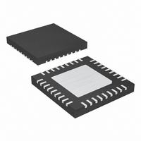
MAX9706ETX+ Maxim Integrated Products, MAX9706ETX+ Datasheet - Page 13

MAX9706ETX+
Manufacturer Part Number
MAX9706ETX+
Description
IC AMP AUDIO 2.3W STER+1 36TQFN
Manufacturer
Maxim Integrated Products
Series
DirectDrive™r
Type
Class Dr
Datasheet
1.MAX9707ETX.pdf
(25 pages)
Specifications of MAX9706ETX+
Output Type
2-Channel (Stereo) with Stereo Headphones and Subwoofer
Max Output Power X Channels @ Load
2.3W x 3 @ 4 Ohm; 95mW x 2 @ 16 Ohm
Voltage - Supply
4.5 V ~ 5.5 V
Features
Depop, Short-Circuit and Thermal Protection, Shutdown
Mounting Type
Surface Mount
Package / Case
36-TQFN Exposed Pad
Lead Free Status / RoHS Status
Lead free / RoHS Compliant
The MAX9706/MAX9707 combine three high-efficiency
Class D amplifiers with an active crossover to provide
stereo highpass outputs, and a mono lowpass output
(Figure 1). All three channels deliver up to 2.3W per
channel into 4Ω when operating from a 5V supply.
An internal active filter processes the stereo inputs (left
and right) into stereo highpass and mono lowpass out-
puts. The crossover frequency is pin-selectable to four
different frequencies to accommodate a variety of
speaker configurations.
The internal Class D amplifiers feature low-EMI, spread-
spectrum outputs. No output filters are required.
The MAX9706 features Maxim’s DirectDrive headphone
amplifier, providing ground-referenced headphone out-
puts without the need for bulky coupling capacitors.
The headphone outputs are capable of delivering
95mW per channel into 16Ω from a 3.3V supply, and
are protected against ESD up to ±8kV.
MAX9706 MAX9707
EP
27
28
29
30
32
33
35
36
—
—
3-Channel, 2.3W, Filterless Class D Amplifiers
PIN
16–19
9–13,
EP
27
28
29
30
32
33
35
36
15
______________________________________________________________________________________
MONO_OUT
Detailed Description
OUTM+
MGAIN
OUTM-
NAME
GAIN2
GAIN1
N.C.
INR
INL
I.C.
EP
Right-Channel Audio Input. Connect the right-channel audio signal to INR with a series
capacitor. INR has a 25kΩ typical input impedance.
Mono Gain Control. Connect MGAIN to GND, V
MONO channel with respect to the left and right channels. See Table 3.
Amplifier Gain-Control Input. Connect GAIN1 and GAIN2 to GND or V
left and right channels. See Tables 2 and 4.
Amplifier Gain-Control Input. Connect GAIN1 and GAIN2 to GND or V
left and right channels. See Tables 2 and 4.
Mono-Speaker Negative Terminal
Mono-Speaker Positive Terminal
Mono Line-Level Output. MONO_OUT is the monaural output of the summed left and right low-
frequency signals.
Left-Channel Audio Input. Connect the left-channel audio signal to INL with a series capacitor.
INL has a 25kΩ typical input impedance.
No Connection. Not internally connected.
Internally Connected. Connect to GND.
Exposed Pad. The external pad lowers the package’s thermal impedance by providing a
direct heat conduction path from the die to the PC board. The exposed pad is not internally
connected. Connect the exposed pad to GND.
Figure 1. Speaker Arrangement
with Active Crossover
RIGHT IN
LEFT IN
FUNCTION
Pin Description (continued)
DD
, or leave floating to set the gain of the
MAX9706
MAX9707
LPF
HPF
HPF
DD
DD
AMPLIFIER
AMPLIFIER
AMPLIFIER
CLASS D
CLASS D
CLASS D
to set the gain of the
to set the gain of the
13


