LM613IWM/NOPB National Semiconductor, LM613IWM/NOPB Datasheet - Page 2
LM613IWM/NOPB
Manufacturer Part Number
LM613IWM/NOPB
Description
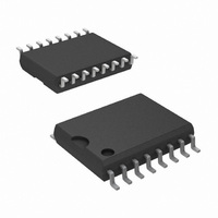
IC COMP/REF/OPAMP DUAL 16SOIC
Manufacturer
National Semiconductor
Series
Super-Block™r
Type
Amplifier, Comparator, Referencer
Datasheet
1.LM613IWMNOPB.pdf
(25 pages)
Specifications of LM613IWM/NOPB
Applications
General Purpose
Mounting Type
Surface Mount
Package / Case
16-SOIC (0.300", 7.5mm Width)
Lead Free Status / RoHS Status
Lead free / RoHS Compliant
Other names
*LM613IWM
*LM613IWM/NOPB
LM613IWM
*LM613IWM/NOPB
LM613IWM
Available stocks
Company
Part Number
Manufacturer
Quantity
Price
Company:

Part Number:
LM613IWM/NOPB
Manufacturer:
Atmel
Quantity:
966


www.national.com
I
V
OPERATIONAL AMPLIFIERS
V
V
I
I
R
C
e
I
CMRR
S
B
OS
n
n
Symbol
S
OS1
OS2
IN
IN
Absolute Maximum Ratings
If Military/Aerospace specified devices are required,
please contact the National Semiconductor Sales Office/
Distributors for availability and specifications.
Electrical Characteristics
These specifications apply for V
unless otherwise specified. Limits in standard typeface are for T
Temperature Range.
Voltage on Any Pin Except V
(referred to V
Current through Any Input Pin
Differential Input Voltage
Storage Temperature Range
Maximum Junction Temp.(Note 4)
(Note 2)
(Note 3)
& V
Military and Industrial
Commercial
R
Pin
Total Supply Current
Supply Voltage Range
V
V
Average V
Input Bias Current
Input Offset Current
Average Offset Current
Input Resistance
Input Capacitance
Voltage Noise
Current Noise
Common-Mode
Rejection Ratio
OS
OS
−
Over Supply
Over V
pin)
Parameter
OS
CM
Drift
R
−
= GND = 0V, V
R
4V ≤ V
4V ≤ V
(4V ≤ V
V
(V
(Note 8)
Differential
Common-Mode
f = 100 Hz, Input Referred
f = 100 Hz, Input Referred
V
CMRR = 20 log (∆V
−65˚C ≤ T
CM
+
LOAD
+
= 30V, 0V ≤ V
− 1.8V), V
= 0V through V
+
+
=
+
≤ 36V (32V for LM613C)
≤ 36V
∞
≤ 32V for LM613C)
−0.3V (Min)
(Note 1)
J
,
36V (Max)
Conditions
≤ +150˚C
+
±
= 5V, V
+
20 mA
150˚C
= 30V, V
±
±
CM
36V
32V
CM
CM
≤ (V
CM
/∆V
=
−
= V
+
2
OS
= 0V
− 1.8V)
J
)
OUT
= 25˚C; limits in boldface type apply over the Operating
Operating Temperature Range
Thermal Resistance,
Junction-to-Ambient (Note 5)
Soldering Information (10 Sec.)
ESD Tolerance (Note 6)
LM613AI, LM613BI:
LM613AM, LM613M:
LM613C:
N Package
WM Package
N Package
WM Package
= 2.5V, I
(Note 7)
Typical
1000
450
550
2.2
2.9
1.5
2.0
1.0
1.5
0.2
0.3
46
43
15
10
11
74
58
95
90
R
4
6
= 100 µA, FEEDBACK pin shorted to GND,
LM613AM
LM613AI
(Note 8)
Limits
1000
940
2.8
3.5
6.0
3.5
6.0
36
36
25
30
80
75
3
4
5
LM613M
LM613C
(Note 8)
LM613I
Limits
1000
1070
2.8
5.0
7.0
5.0
7.0
32
32
35
40
75
70
3
4
5
0˚C ≤ T
−55˚C to +125˚C
−40˚C to +85˚C
J
mV (Max)
mV (Max)
mV (Max)
mV (Max)
100˚C/W
150˚C/W
µA (Max)
µA (Max)
nA (Max)
nA (Max)
nA (Max)
nA (Max)
dB (Min)
dB (Min)
V (Max)
V (Max)
≤ +70˚C
V (Min)
V (Min)
Units
µV/˚C
(Max)
pA/˚C
260˚C
220˚C
±
MΩ
pF
1 kV
Related parts for LM613IWM/NOPB
Image
Part Number
Description
Manufacturer
Datasheet
Request
R

Part Number:
Description:
IC, OP-AMP, 800KHZ, 0.7V/µs, SOIC-16
Manufacturer:
National Semiconductor
Datasheet:
Part Number:
Description:
National Semiconductor [8-Bit D/A Converter]
Manufacturer:
National Semiconductor
Datasheet:
Part Number:
Description:
National Semiconductor [Media Coprocessor]
Manufacturer:
National Semiconductor
Datasheet:
Part Number:
Description:
Digitally Controlled Tone and Volume Circuit with Stereo Audio Power Amplifier, Microphone Preamp Stage and National 3D Sound
Manufacturer:
National Semiconductor
Datasheet:
Part Number:
Description:
Digitally Controlled Tone and Volume Circuit with Stereo Audio Power Amplifier, Microphone Preamp Stage and National 3D Sound
Manufacturer:
National Semiconductor
Datasheet:
Part Number:
Description:
AC97 Rev 2 Codec with Sample Rate Conversion and National 3D Sound
Manufacturer:
National Semiconductor
Part Number:
Description:
Manufacturer:
National Semiconductor
Datasheet:
Part Number:
Description:
Manufacturer:
National Semiconductor
Datasheet:
Part Number:
Description:
General Purpose, Low Voltage, Low Power, Rail-to-Rail Output Operational Amplifiers
Manufacturer:
National Semiconductor
Datasheet:
Part Number:
Description:
8-bit 20 MSPS flash A/D converter.
Manufacturer:
National Semiconductor
Datasheet:
Part Number:
Description:
Low Noise Quad Operational Amplifier
Manufacturer:
National Semiconductor
Datasheet:
Part Number:
Description:
Quad Differential Line Receivers
Manufacturer:
National Semiconductor
Datasheet:
Part Number:
Description:
Quad High Speed Trapezoidal? Bus Transceiver
Manufacturer:
National Semiconductor
Datasheet:
Part Number:
Description:
Dual Line Receiver
Manufacturer:
National Semiconductor
Datasheet: