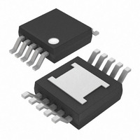
MAX3269CUB+ Maxim Integrated Products, MAX3269CUB+ Datasheet - Page 13

MAX3269CUB+
Manufacturer Part Number
MAX3269CUB+
Description
IC AMP LIMITING 1.25GBPS 10-UMAX
Manufacturer
Maxim Integrated Products
Type
Limiting Amplifierr
Datasheet
1.MAX3768CUB.pdf
(17 pages)
Specifications of MAX3269CUB+
Applications
Optical Networks
Mounting Type
Surface Mount
Package / Case
10-MSOP Exposed Pad, 10-HMSOP, 10-eMSOP
Lead Free Status / RoHS Status
Lead free / RoHS Compliant
In an optical receiver, the electrical power change at
the limiting amplifier is 2x the optical power change.
As an example, if a receiver’s optical input power (x)
increases by a factor of two, and the preamplifier is lin-
ear, then the voltage input to the limiting amplifier also
increases by a factor of two.
The optical power change is 10log(2x / x) = 10log(2) =
+3dB.
At the limiting amplifier, the electrical power change is:
The MAX3264/MAX3265/MAX3268/MAX3269/MAX3765s’
typical voltage hysteresis is 4.4dB. This provides an opti-
cal hysteresis of 2.2dB.
In a GBIC application, the GBIC’s LOS output must be
high impedance when V
shows the recommended circuit to maintain high
impedance. ESD protection diodes on the MAX3264/
MAX3265/MAX3268/MAX3269/MAX3765/MAX3768
LOS outputs can be turned on when V
V
The standard PECL termination (50Ω to V
recommended for best performance and output char-
acteristics (see Figure 1). The data outputs operate at
high speed and should always drive transmission lines
with matched, balanced terminations.
Figure 9 shows an alternate method for terminating the
data outputs. The technique provides approximately
8mA DC bias current, with a 45Ω AC load, for the out-
put termination. This technique is useful for viewing the
output on an oscilloscope or changing the PECL refer-
ence voltage.
For high current density and reliable operation, the
MAX3264/MAX3265/MAX3268/MAX3269 use gold met-
alization. Make connections to the dice with gold wire
only, and use ballbonding techniques (wedge bonding
is not recommended). Die-pad size is 4-mils square,
with a 6-mil pitch. Die thickness is 15 mils (0.375mm).
10log
CC_
MODULE.
(
2V
V
IN
IN
2
)
2
/ R
/ R
IN
Applications Information
IN
______________________________________________________________________________________
=
10log(2 )
CC_
MODULE = GND. Figure 8
GBIC Loss of Signal
PECL Terminations
2
Optical Hysteresis
Wire Bonding Dice
=
+3.0V to +5.5V, 1.25Gbps/2.5Gbps
20log(2)
CC_
CC
= +
HOST >
- 2V) is
6dB
Figure 8. Recommended GBIC LOS Circuit
Figure 9. Alternative PECL Termination
DRIVING 50Ω TO GROUND
GBIC MODULE
MAX3264
MAX3265
MAX3268
MAX3269
MAX3765
MAX3768
MAX3268
MAX3269
MAX3768
Limiting Amplifiers
V
CC_
OUT+
OUT-
MODULE
LOS
470Ω
470Ω
GENERAL-
PURPOSE
NPN
HOST
V
CC_
50Ω
50Ω
HOST
4.7kΩ
13


