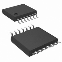
LM6588MT/NOPB National Semiconductor, LM6588MT/NOPB Datasheet - Page 13

LM6588MT/NOPB
Manufacturer Part Number
LM6588MT/NOPB
Description
IC OPAMP TFT-LCD QD 16V 14TSSOP
Manufacturer
National Semiconductor
Series
VIP10™r
Datasheet
1.LM6588MANOPB.pdf
(16 pages)
Specifications of LM6588MT/NOPB
Applications
TFT-LCD Panels: Gamma Buffer, VCOM Driver
Output Type
Rail-to-Rail
Number Of Circuits
4
-3db Bandwidth
24MHz
Slew Rate
15 V/µs
Current - Supply
800µA
Current - Output / Channel
230mA
Voltage - Supply, Single/dual (±)
5 V ~ 16 V, ±2.5 V ~ 8 V
Mounting Type
Surface Mount
Package / Case
14-TSSOP (0.173", 4.40mm Width)
Op Amp Type
Low Power
No. Of Amplifiers
4
Bandwidth
15.4MHz
Supply Voltage Range
5V To 16V
Amplifier Case Style
TSSOP
No. Of Pins
14
Operating Temperature Range
-40°C To
Rohs Compliant
Yes
Number Of Channels
4
Voltage Gain Db
106 dB
Common Mode Rejection Ratio (min)
70 dB
Input Offset Voltage
4 mV at 5 V
Operating Supply Voltage
9 V, 12 V, 15 V
Supply Current
4 mA at 5 V
Maximum Operating Temperature
+ 85 C
Maximum Dual Supply Voltage
+/- 8 V
Minimum Operating Temperature
- 40 C
Lead Free Status / RoHS Status
Lead free / RoHS Compliant
Other names
*LM6588MT
*LM6588MT/NOPB
LM6588MT
*LM6588MT/NOPB
LM6588MT
TFT Display Application
GAMMA BUFFER
Illumination in a TFT display, also referred to as grayscale, is
set by a series of discrete voltage levels that are applied to
each LCD pixel. These voltage levels are generated by
resistive DAC networks that reside inside each of the column
driver ICs. For example, a column driver with 64 Grayscale
levels has a two 6 bit resistive DACs. Typically, the two
DACs will have their 64 resistors grouped into four seg-
ments, as shown in Figure 8. Each of these segments is
connected to external voltage lines, VGMA1 to VGMA10,
which are the Gamma Levels. VGMA1 to VGMA5 set gray-
scale voltage levels that are positive with respect to V
(high polarity gamma levels). VGMA6 to VGMA10 set gray-
scale voltages negative with respect to V
gamma levels).
Figure 9 shows how column drivers in a TFT display are
connected to the gamma levels. VGMA1, VGMA5, VGMA6,
and VGMA10 are driven by the Gamma Buffers. These
buffers serve as low impedance voltage sources that gener-
ate the display’s gamma levels. The Gamma Buffers’ outputs
are set by a simple resistive ladder, as shown in Figure 9.
Note that VGMA2 to VGMA4 and VGMA7 to VGMA9 are
usually connected to the column drivers even though they
are not driven by external buffers. Doing so, forces the
gamma levels in all the column drivers to be identical, mini-
mizing grayscale mismatch between column drivers. Refer-
ring again to Figure 9, the resistive load of a column driver
DAC (i.e. resistance between GMA1 to GMA5) is typically
10kΩ to 15kΩ. On a typical display such as XGA, there can
be up to 10 column drivers, so the total resistive load on a
Gamma Buffer output can be as low as 1kΩ. The voltage
between VGMA1 and VGMA5 can range from 3V to 6V,
depending on the type of TFT panel. Therefore, maximum
load current supplied by a Gamma Buffer is approximately
6V/1kΩ = 6mA, which is a relatively light load for most op
amps. In many displays, VGMA1 can be less than 500mV
below V
ground. Under these conditions, an op amp used for the
Gamma Buffer must have rail-to-rail inputs and outputs, like
the LM6588.
FIGURE 8. Simplified Schematic of Column Driver IC
DD
, and VGMA10 can be less than 500mV above
COM
(Continued)
(low polarity
20073433
COM
13
Another important specification for Gamma Buffers is small
signal bandwidth and slew rate. When column drivers select
which voltage levels are written to a row of pixels, their
internal DACs inject current spikes into the Gamma Lines.
This generates voltage transients at the Gamma Buffer out-
puts, and they should settle-out in less than 1µs to insure a
steady output voltage from the column drivers. Typically,
these transients have a maximum amplitude of 2V, so a
gamma buffer must have sufficient bandwidth and slew rate
to recover from a 2V transient in 1µs or less.
Figure 10 illustrates how an op amp responds to a large-
signal transient. When such a transient occurs at t = 0, the
output does not start changing until T
amp’s propagation delay time (typically 20ns for the
LM6588). The output then changes at the op amp’s slew rate
from t = T
to its final value (V
small-signal frequency response. Although propagation de-
FIGURE 10. Large Signal Transient Response of an
FIGURE 9. Basic Gamma Buffer Configuration
PD
to T
SR
F
Operational Amplifier
. From t = T
) at a speed determined by the op amp’s
SR
to T
SE
PD
T, the output settles
, which is the op
www.national.com
20073434
20073435


