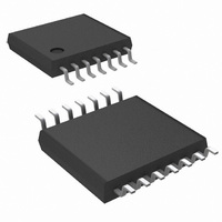
LMH6722MT/NOPB National Semiconductor, LMH6722MT/NOPB Datasheet - Page 11

LMH6722MT/NOPB
Manufacturer Part Number
LMH6722MT/NOPB
Description
IC OP AMP QUAD VIDEO 14-TSSOP
Manufacturer
National Semiconductor
Series
PowerWise®, VIP10™r
Datasheet
1.LMH6714MFNOPB.pdf
(16 pages)
Specifications of LMH6722MT/NOPB
Applications
Current Feedback
Number Of Circuits
4
-3db Bandwidth
400MHz
Slew Rate
1800 V/µs
Current - Supply
5.6mA
Current - Output / Channel
70mA
Voltage - Supply, Single/dual (±)
8 V ~ 12.5 V, ±4 V ~ 6.25 V
Mounting Type
Surface Mount
Package / Case
14-TSSOP (0.173", 4.40mm Width)
Lead Free Status / RoHS Status
Lead free / RoHS Compliant
Other names
*LMH6722MT
*LMH6722MT/NOPB
LMH6722MT
LMH6722MTNOPB
LMH6722MTNOPB
*LMH6722MT/NOPB
LMH6722MT
LMH6722MTNOPB
LMH6722MTNOPB
WIDE BAND DIGITAL PROGRAMMABLE GAIN AMPLIFIER (LMH6720 ONLY)
As shown in
to construct a digitally controlled programmable gain amplifi-
er. Each amplifier is configured to provide a digitally se-
lectable gain. To provide for accurate gain settings, 1% or
AMPLITUDE EQUALIZATION
Sending signals over coaxial cable greater than 50 meters in
length will attenuate high frequency signal components much
more than lower frequency components. An equalizer can be
made to pre emphasize the higher frequency components so
that the final signal has less distortion. This process can be
done at either end of the cable. The circuit in
a receiver with some additional components in the feedback
loop to equalize the incoming signal. The RC networks peak
the signal at higher frequencies. This peaking is a piecewise
linear approximation of the inverse of the frequency response
of the coaxial cable.
ization on a digital signal that has passed through 150 meters
of coaxial cable.
Figure 6
Figure 10
Figure 9
and
Figure 7
FIGURE 6. Wideband Digitally Controlled Programmable Gain Amplifier
shows a Bode plot of the frequency
shows the effect of this equal-
the LMH6720 can be used
Figure 8
FIGURE 7. PGA Output
shows
Channel Switching
11
better tolerance is recommended on the feedback and gain
resistors. The gain provided by each digital code is arbitrary
through selection of the feedback and gain resistor values.
response of the circuit in
ed to design the pole and zero frequencies.
a network analyzer plot of an LMH6714/LMH6720/LMH6722
with the following component values:
R
R1 = 450Ω
C1 = 470pF
R2 = 91Ω
C2 = 68pF
G
= 309Ω
20056520
Figure 8
along with equations need-
Figure 11
20056519
www.national.com
shows


