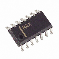
MAX4314ESD+ Maxim Integrated Products, MAX4314ESD+ Datasheet - Page 16

MAX4314ESD+
Manufacturer Part Number
MAX4314ESD+
Description
IC AMP/VIDEO/MUX LP 4CH 14-SOIC
Manufacturer
Maxim Integrated Products
Datasheet
1.MAX4310ESA.pdf
(18 pages)
Specifications of MAX4314ESD+
Applications
4:1 Multiplexer-Amplifier
Output Type
Rail-to-Rail
Number Of Circuits
1
-3db Bandwidth
127MHz
Slew Rate
430 V/µs
Current - Supply
6.9mA
Current - Output / Channel
95mA
Voltage - Supply, Single/dual (±)
4 V ~ 10.5 V, ±2 V ~ 5.25 V
Mounting Type
Surface Mount
Package / Case
14-SOIC (0.154", 3.90mm Width)
Number Of Channels
4
Operating Supply Voltage
12 V
Supply Current
560 uA
Minimum Operating Temperature
- 40 C
Maximum Operating Temperature
+ 85 C
Bandwidth
90 MHz
Maximum Dual Supply Voltage
5.25 V
Minimum Dual Supply Voltage
2 V
Supply Voltage (max)
10.5 V
Supply Voltage (min)
4 V
Lead Free Status / RoHS Status
Lead free / RoHS Compliant
High-Speed, Low-Power, Single-Supply
Multichannel, Video Multiplexer-Amplifiers
The multiplexer architecture of the MAX4310–MAX4315
ensures that no two input channels are ever connected
together. Channel selection is accomplished by apply-
ing a binary code to channel address inputs. The
address decoder selects input channels, as shown in
Table 2. All digital inputs are CMOS compatible.
Figures 10 and 11 show the evaluation board and pre-
sent a suggested layout for the circuits. This board was
developed using the techniques described in the
Layout and Power-Supply Bypassing section. The
smallest available surface-mount resistors were used
TRANSISTOR COUNT: 156
16
______________________________________________________________________________________
High-Speed Evaluation Board
Chip Information
5
4
+4V TO +10.5V
Digital Interface
IN1
IN0
MAX4313
1
A0
V
EE
6
V
CC
SHDN
3
2
7
500Ω
500Ω
GND
OUT
0.1 µF
8
for feedback and back-termination to minimize their dis-
tance from the part, reducing the capacitance associat-
ed with longer lead lengths.
SMA connectors were used for best high-frequency
performance. Inputs and outputs do not match a 75Ω
line, but this does not affect performance since dis-
tances are extremely short. However, in applications
that require lead lengths greater than one-quarter of the
wavelength of the highest frequency of interest, use
constant-impedance traces. Fully assembled evaluation
boards are available for the MAX4313 in an SO pack-
age.
For the latest package outline information, go to
www.maxim-ic.com/packages.
75Ω
PACKAGE TYPE
14 Narrow SO
16 Narrow SO
16 QSOP
8 µMAX
75Ω CABLE
8 SO
Typical Operating Circuit
75Ω
OUTPUT
VIDEO
PACKAGE CODE
Package Information
S14-1
S16-1
E16-1
U8-1
S8-4
DOCUMENT NO.
21-0041
21-0036
21-0041
21-0041
21-0055


