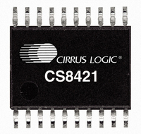
CS8421-CZZ Cirrus Logic Inc, CS8421-CZZ Datasheet - Page 18

CS8421-CZZ
Manufacturer Part Number
CS8421-CZZ
Description
IC SAMPLE RATE CONVERTER 20TSSOP
Manufacturer
Cirrus Logic Inc
Type
Sample Rate Converterr
Datasheet
1.CS8421-CZZ.pdf
(36 pages)
Specifications of CS8421-CZZ
Package / Case
20-TSSOP
Applications
CD-R, DAT, DVD, MD, VTR
Mounting Type
Surface Mount
Operating Supply Voltage
3.3 V / 5.0 V
Operating Temperature Range
- 10 C to + 70 C
Mounting Style
SMD/SMT
Lead Free Status / RoHS Status
Lead free / RoHS Compliant
For Use With
598-1018 - BOARD EVAL FOR CS8421
Lead Free Status / Rohs Status
Lead free / RoHS Compliant
Other names
598-1126-5
Available stocks
Company
Part Number
Manufacturer
Quantity
Price
Company:
Part Number:
CS8421-CZZ
Manufacturer:
CIRRUS
Quantity:
1 223
Part Number:
CS8421-CZZ
Manufacturer:
CIRRUS
Quantity:
20 000
18
4.2
The CS8421 uses the resistors attached to the MS_SEL, SAIF, and SAOF pins to determine the modes of operation.
After reset, the resistor value and condition (VL or GND) are sensed. This operation will take approximately 4 s to
complete. The SRC_UNLOCK pin will remain high and the SDOUT pin will be muted until the mode detection se-
quence has completed. After this, if all clocks are stable, SRC_UNLOCK will be brought low when audio output is
valid and normal operation will occur.
the 1.0 k option is selected for MS_SEL, SAIF, or SAOF, the resistor connected to that pin may be replaced by a
direct connection to VL or GND as appropriate.
The resistor attached to each mode-selection pin should be placed physically close to the CS8421. The end of the
resistor not connected to the mode selection pins should be connected as close as possible to VL and GND to min-
imize noise.
I/OLRCK
I/OLRCK
I/OSCLK
I/OSCLK
I/OLRCK
I/OSCLK
SDOUT
SDOUT
SDOUT
SDIN
SDIN
SDIN
Mode Selection
Tables
M S B
M S B
MSB Extended
1, 2, and
3
Figure 9. Serial Audio Interface Format - Right-Justified
Figure 8. Serial Audio Interface Format - Left-Justified
show the pin functions and their corresponding settings.
Channel A
Channel A
Channel A
MSB
MSB
Figure 7. Serial Audio Interface Format - I²S
Tables
1, 2, and
L S B
L S B
3
LSB
LSB
show the pin functions and their corresponding settings. If
M S B
M S B
MSB Extended
Channel B
Channel B
Channel B
MSB
MSB
L S B
L S B
LSB
LSB
CS8421
MSB
DS641F5
MSB


