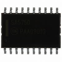
SA575DG ON Semiconductor, SA575DG Datasheet - Page 5

SA575DG
Manufacturer Part Number
SA575DG
Description
IC COMPANDOR 2CHAN GAIN 20-SOIC
Manufacturer
ON Semiconductor
Type
Compandorr
Datasheet
1.SA575DTBR2.pdf
(16 pages)
Specifications of SA575DG
Applications
Cellular Radio, Mixers
Mounting Type
Surface Mount
Package / Case
20-SOIC (7.5mm Width)
Package
20SOIC W
Operating Temperature
-40 to 85 °C
Product
General Purpose Audio Amplifiers
Output Type
Programmable Analog
Available Set Gain
+/- 1.5 dB
Common Mode Rejection Ratio (min)
80 dB
Thd Plus Noise
0.12 %
Operating Supply Voltage
5 V
Supply Current
4.2 mA
Maximum Power Dissipation
1116 mW
Maximum Operating Temperature
+ 85 C
Mounting Style
SMD/SMT
Audio Load Resistance
600 Ohms
Input Bias Current (max)
+/- 1 uA
Input Offset Voltage
3 mV
Minimum Operating Temperature
- 40 C
Supply Voltage (max)
7 V
Supply Voltage (min)
3 V
Lead Free Status / RoHS Status
Lead free / RoHS Compliant
Other names
SA575DG
SA575DGOS
SA575DGOS
Available stocks
Company
Part Number
Manufacturer
Quantity
Price
Company:
Part Number:
SA575DG
Manufacturer:
PANASONIC
Quantity:
201
Part Number:
SA575DG
Manufacturer:
ON/安森美
Quantity:
20 000
Expandor
The variable gain cell and the rectifier cell are in the signal
input path. The V
maximum headroom without clipping. The 0 dB ref is
100 mV
output is AC coupled through C
and outputs are AC coupled, then C
eliminated, thus requiring only one external component,
C
so any offset voltage between Pins 4 and 9 will cause small
offset error current in the rectifier cell. This will affect the
4
The typical expandor configuration is shown in Figure 2.
. The variable gain cell and rectifier cell are DC coupled
RMS
EXP IN
. The input is AC coupled through C
REF
10mF
C
5
is always 1/2 V
4, 16
9, 11
3
. If in a system the inputs
3.8kW
10kW
Figure 2. Typical Expandor Configuration
CC
3
and C
C
to provide the
4
D
G
5, 15
5
5
, and the
2.2mF
can be
http://onsemi.com
SA575
8
5
V
REF
S
accuracy of the gain cell. This can be improved by using an
extra capacitor from the input to Pin 4 and eliminating the
DC connection between Pins 4 and 9.
time constant is given by Equation 1 and Equation 2,
respectively.
10kW
The expandor gain expression and the attack and release
7, 13
6, 14
t
Expandor gain =
R
= t
where V
A
= 10 kW x C
IN
10mF
C
(avg) = 0.95V
3
RECT
3.8 kW x 100 mA
4V
= 10 kW x C
IN
IN(RMS)
(avg)
EXP OUT
2
4
(eq. 1)
(eq. 2)


