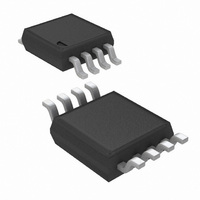
LMC6772AIMM/NOPB National Semiconductor, LMC6772AIMM/NOPB Datasheet - Page 12

LMC6772AIMM/NOPB
Manufacturer Part Number
LMC6772AIMM/NOPB
Description
IC COMP DUAL MICRPWR CMOS 8-MSOP
Manufacturer
National Semiconductor
Type
General Purposer
Datasheet
1.LMC6772AIMNOPB.pdf
(16 pages)
Specifications of LMC6772AIMM/NOPB
Number Of Elements
2
Output Type
Open Drain
Voltage - Supply
2.7 V ~ 15 V, ±1.35 V ~ 7.5 V
Mounting Type
Surface Mount
Package / Case
8-TSSOP, 8-MSOP (0.118", 3.00mm Width)
Number Of Elements
2
Technology
CMOS
Input Offset Voltage
5@5VmV
Input Bias Current (typ)
40pA
Single Supply Voltage (typ)
3/5/9/12V
Dual Supply Voltage (typ)
±3/±5V
Supply Current (max)
0.02@5VmA
Common Mode Rejection Ratio
75dB
Voltage Gain In Db
100dB
Power Supply Rejection Ratio
80dB
Power Supply Requirement
Single/Dual
Single Supply Voltage (min)
2.7V
Single Supply Voltage (max)
15V
Dual Supply Voltage (min)
±1.35V
Dual Supply Voltage (max)
±7.5V
Operating Temp Range
-40C to 85C
Operating Temperature Classification
Industrial
Mounting
Surface Mount
Pin Count
8
Package Type
MSOP
Comparator Type
Micropower
No. Of Comparators
2
Response Time
4µs
Ic Output Type
Open Drain
Supply Current
20µA
Supply Voltage Range
2.7V To 15V
Amplifier Case Style
MSOP
No. Of Pins
8
Rohs Compliant
Yes
Lead Free Status / RoHS Status
Lead free / RoHS Compliant
Other names
LMC6772AIMM
LMC6772AIMMTR
LMC6772AIMMTR
www.national.com
OSCILLATOR
The circuit shown above provides output signals at a pre-
scribed time interval from a time reference and automatically
resets the output when the input returns to ground. Consider
the case of V
ground. This implies that the outputs of comparators 1, 2, and
3 are also at ground. When an input signal is applied, the out-
put of comparator 4 swings high and C charges exponentially
FIGURE 8. Square Wave Generator
IN
= 0. The output of comparator 4 is also at
Time Delay Generator
FIGURE 9. Time Delay Generator
1234731
12
Figure 8
wave generator circuit. The total hysteresis of the loop is set
by R
discharge paths for the capacitor C. The charge path is set
through R
RC time constant of R
for the capacitor is set by R
the pulses can be changed by varying R
can be altered by R
changed by varying both R
through R. This is indicated above. The output voltages of
comparators 1, 2, and 3 swtich to the high state when V
rises above the reference voltages V
amount of hysteresis has been provided to insure fast switch-
ing when the RC time constant is chosen to give long delay
times.
1
, R
2
shows the application of the LMC6772 in a square
4
and R
and D
3
1
. R
. So, the pulse width t
4
4
. The frequency of the output can be
4
and R
and C. Similarly, the discharge path
5
4
and D
and R
5
provide separate charge and
2
. Thus, the time t
5
.
A
1234732
1
, V
5
, and the pulse width
is determined by the
B
and V
C
2
. A small
between
C1


