MAX9028EBT+T Maxim Integrated Products, MAX9028EBT+T Datasheet - Page 10
MAX9028EBT+T
Manufacturer Part Number
MAX9028EBT+T
Description
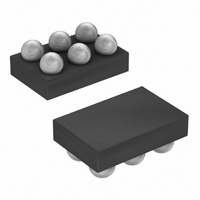
IC COMPARATOR BTR 6-UCSP
Manufacturer
Maxim Integrated Products
Series
Beyond-the-Rails™r
Type
General Purposer
Datasheet
1.MAX9027EBTT.pdf
(13 pages)
Specifications of MAX9028EBT+T
Number Of Elements
1
Output Type
Open-Drain, Rail-to-Rail
Voltage - Supply
1.8 V ~ 5.5 V
Mounting Type
Surface Mount
Package / Case
6-UCSP®
Lead Free Status / RoHS Status
Lead free / RoHS Compliant


UCSP, 1.8V, Nanopower, Beyond-the-Rails
Comparators With/Without Reference
The MAX9025–MAX9028s’ internal +1.236V reference
has a typical temperature coefficient of 40ppm/°C over
the full -40°C to +85°C temperature range. The reference
is a very-low-power bandgap cell, with a typical 35kΩ
output impedance. REF can source and sink up to
100nA to external circuitry. For applications needing
increased drive, buffer REF with a low input-bias current
op amp such as the MAX4162. Most applications require
no REF bypass capacitor. For noisy environments or fast
V
from REF to GND.
The MAX9025–MAX9028 are ideally suited for use with
most battery-powered systems. Table 1 lists a variety of
battery types, capacities, and approximate operating
times for the MAX9025–MAX9028, assuming nominal
conditions.
Many comparators oscillate in the linear region of opera-
tion because of noise or undesired parasitic feedback.
This tends to occur when the voltage on one input is
equal or very close to the voltage on the other input. The
MAX9025–MAX9028 have internal 4mV hysteresis to
counter parasitic effects and noise.
The hysteresis in a comparator creates two trip points:
one for the rising input voltage (V
falling input voltage (V
between the trip points is the hysteresis (V
the comparator’s input voltages are equal, the hystere-
sis effectively causes one comparator input to move
Table 1. Battery Applications Using MAX9025–MAX9028
10
Alkaline
(2 Cells)
Nickel-
Cadmium
(2 Cells)
Lithium-Ion
(1 Cell)
Nickel-Metal-
Hydride
(2 Cells)
CC
BATTERY
transients, connect a 1nF to 10nF ceramic capacitor
TYPE
______________________________________________________________________________________
Low-Voltage, Low-Power Operation
Reference (MAX9025/MAX9026)
RECHARGEABLE
Applications Information
Yes
Yes
Yes
No
THF
) (Figure 2). The difference
Internal Hysteresis
THR
V
FRESH
) and one for the
3.0
2.4
3.5
2.4
(V)
HB
V
). When
END-OF-LIFE
(V)
1.8
1.8
2.7
1.8
quickly past the other, thus taking the input out of the
region where oscillation occurs. Figure 2 illustrates the
case in which IN- has a fixed voltage applied, and IN+
is varied. If the inputs were reversed, the figure would
be the same, except with an inverted output.
In applications requiring more than the internal 4mV
hysteresis of the MAX9025–MAX9028, additional hys-
teresis can be added with external components.
Because the MAX9025–MAX9028 are intended for very
low-power systems, care should be taken to minimize
power dissipation in the additional circuitry.
Regardless of which approach is taken, the external
hysteresis will be V
range of battery-powered systems, the hysteresis can
change as much as 40%. This must be considered
during design.
Figure 1. MAX9025/MAX9026 Voltage Reference Output
Equivalent Circuit
CAPACITY,
AA SIZE
(mA-H)
2000
1000
1000
750
MAX9025/MAX9026
OPERATING TIME
CC
BANDGAP
Adding External Hysteresis
V
V
1.8 x 10
0.9 x 10
0.9 x 10
680,000
CC
EE
dependent. Over the full discharge
(hr)
6
6
6
MAX9027/MAX9028
OPERATING TIME
REF
1.07 x 10
2.8 x 10
1.4 x 10
1.4 x 10
(hr)
6
6
6
6
Related parts for MAX9028EBT+T
Image
Part Number
Description
Manufacturer
Datasheet
Request
R

Part Number:
Description:
MAX7528KCWPMaxim Integrated Products [CMOS Dual 8-Bit Buffered Multiplying DACs]
Manufacturer:
Maxim Integrated Products
Datasheet:
Part Number:
Description:
Single +5V, fully integrated, 1.25Gbps laser diode driver.
Manufacturer:
Maxim Integrated Products
Datasheet:
Part Number:
Description:
Single +5V, fully integrated, 155Mbps laser diode driver.
Manufacturer:
Maxim Integrated Products
Datasheet:
Part Number:
Description:
VRD11/VRD10, K8 Rev F 2/3/4-Phase PWM Controllers with Integrated Dual MOSFET Drivers
Manufacturer:
Maxim Integrated Products
Datasheet:
Part Number:
Description:
Highly Integrated Level 2 SMBus Battery Chargers
Manufacturer:
Maxim Integrated Products
Datasheet:
Part Number:
Description:
Current Monitor and Accumulator with Integrated Sense Resistor; ; Temperature Range: -40°C to +85°C
Manufacturer:
Maxim Integrated Products
Part Number:
Description:
TSSOP 14/A�/RS-485 Transceivers with Integrated 100O/120O Termination Resis
Manufacturer:
Maxim Integrated Products
Part Number:
Description:
TSSOP 14/A�/RS-485 Transceivers with Integrated 100O/120O Termination Resis
Manufacturer:
Maxim Integrated Products
Part Number:
Description:
QFN 16/A�/AC-DC and DC-DC Peak-Current-Mode Converters with Integrated Step
Manufacturer:
Maxim Integrated Products
Part Number:
Description:
TDFN/A/65V, 1A, 600KHZ, SYNCHRONOUS STEP-DOWN REGULATOR WITH INTEGRATED SWI
Manufacturer:
Maxim Integrated Products
Part Number:
Description:
Integrated Temperature Controller f
Manufacturer:
Maxim Integrated Products
Part Number:
Description:
SOT23-6/I�/45MHz to 650MHz, Integrated IF VCOs with Differential Output
Manufacturer:
Maxim Integrated Products
Part Number:
Description:
SOT23-6/I�/45MHz to 650MHz, Integrated IF VCOs with Differential Output
Manufacturer:
Maxim Integrated Products
Part Number:
Description:
EVALUATION KIT/2.4GHZ TO 2.5GHZ 802.11G/B RF TRANSCEIVER WITH INTEGRATED PA
Manufacturer:
Maxim Integrated Products
Part Number:
Description:
QFN/E/DUAL PCIE/SATA HIGH SPEED SWITCH WITH INTEGRATED BIAS RESISTOR
Manufacturer:
Maxim Integrated Products
Datasheet: