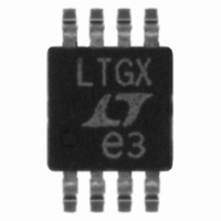
LT1675CMS8-1#PBF Linear Technology, LT1675CMS8-1#PBF Datasheet - Page 9

LT1675CMS8-1#PBF
Manufacturer Part Number
LT1675CMS8-1#PBF
Description
IC MUX RGB SGL HS W/CFA 8-MSOP
Manufacturer
Linear Technology
Type
MUXr
Datasheet
1.LT1675CS8-1PBF.pdf
(16 pages)
Specifications of LT1675CMS8-1#PBF
Applications
Drivers, Processing, Switching
Mounting Type
Surface Mount
Package / Case
8-MSOP, Micro8™, 8-uMAX, 8-uSOP,
Lead Free Status / RoHS Status
Lead free / RoHS Compliant
Available stocks
Company
Part Number
Manufacturer
Quantity
Price
APPLICATIONS
Power Supplies
The LT1675 will function with supply voltages below ±2V
(4V total), however, to ensure a full 1V
(2V
should be between ±4V to ±6V. The LT1675 is designed
to operate on ±5V, and at no time should the supplies
exceed ±6V. The power supplies should be bypassed with
quality tantalum capacitors. It may be necessary to add a
0.01µF or 0.1µF in parallel with the tantalum capacitors if
there is excessive ringing on the output waveform. Even
though the LT1675 is well behaved, bypass capacitors
should be placed as close to the LT1675 as possible.
Smallest Package and PC Board Space
The LT1675 has the internal gain set for + 2V/V or 6dB,
because it is designed to drive a double-terminated 50Ω or
75Ω cable that has an inherent 6dB loss. There are several
advantages to setting the gain internally. This topology
eliminates six gain set resistors, reduces the pin count of
the package and eliminates stray capacitance on the
sensitive feedback node. The LT1675 fits into the small
RED OUT
P-P
SELECT
PIN 10
PIN 15
at the output pins), the power supply voltage
0V
3V
RED 1 = 1V, RED 2 = 0V
MEASURED BETWEEN 75Ω BACK TERMINATION
AND 75Ω LOAD
Figure 1. Toggling at 25MHz
U
INFORMATION
U
W
P-P
1675 F01
video signal
U
1V/DIV
500mV/DIV
SSOP package, and these advantages lead to the smallest
PC board footprint with enhanced performance. The
LT1675-1 eliminates two gain set resistors and is available
in the tiny MSOP package and the cost-effective SO-8
package.
Fast Switching
The key to the LT1675 fast switching speed is Linear
Technology’s proprietary high speed bipolar process.
Internal switches can change state in less than 1ns, but the
output of the MUX switches in about 2.5ns, as shown in
Figure 1. The additional delay is due to the finite bandwidth
and the slew rate of the current feedback amplifier that
drives the cable.
For minimum ringing, it is important to minimize the load
capacitance on the output of the part. This is normally not
a problem in a controlled impedance environment, but
stray PC board capacitance and scope probe capacitance
can degrade the pulse fidelity. Figure 2 shows the
response of the output to various capacitive loads mea-
sured with a 10pF scope probe.
C
C
L
L
C
L
= 20pF
= 10pF
= 0pF
Figure 2. Response to Capacitive Loads
MEASURED AT PIN 15
R
L
= 150Ω, 10pF SCOPE PROBE
LT1675/LT1675-1
1675 F02
2V/DIV
16751fb
9


