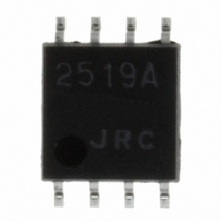
NJM2519AM NJR, NJM2519AM Datasheet - Page 2

NJM2519AM
Manufacturer Part Number
NJM2519AM
Description
IC RF MOD FOR VHF BAND 8-DMP
Manufacturer
NJR
Type
RF Modulatorr
Datasheet
1.NJM2519AM.pdf
(8 pages)
Specifications of NJM2519AM
Applications
VHF Band
Mounting Type
Surface Mount
Package / Case
*
Lead Free Status / RoHS Status
Contains lead / RoHS non-compliant
NJM2519A
- 2 -
Supply Voltage
Power Dissipation
Input Voltage
Operating Temperature Range
Storage Temperature Range
Operating Voltage
Operating Current
Video Output Level
Video Modulation Depth
Video Limiter Modulation
Depth
Differential Gain
Differential Phase
Picture-to-sound Ratio
Sound FM Modulation
Sensitivity
Audio Distortion
Audio Signal-to-noise
Ratio
Maximum Sound FM
Modulation
(Note 1) Because AC characteristics largely depends on application circuit, these parameters are specified
ABSOLUTE MAXIMUM RATINGS
RECOMMENDED OPERATING VOLTAGE RANGE
ELECTRICAL CHARACTERISTICS
Parameter
Parameter
by the DC characteristics as shown in next page.
Parameter
(Note 1)
(Note 1)
(Note 1)
(Note 1)
No video/audio input signal,
Video input signal(Pin1)=0.5V
Video input signal(Pin1)=0.5V
Video input signal(Pin1)=1.0V
Video input signal(Pin1)=0.5V
Staircase
Video input signal(Pin1)=0.5V
Staircase
Video input signal(Pin1)=0.5V
Deviation of fs per 100mV
Audio input signal(Pin7)=0.05V
1kHz sine wave
Sound Modulation 60%
1kHz sine wave
Audio input signal(Pin7)=1.0V
1kHz sine wave
Symbol
V
T
T
P
V
CC
opr
stg
D
I
Condition
Condition
-40 to +125
-0.3 to V
-20 to +75
Ratings
300
PP
PP
PP
PP
PP
PP
PP
7
PP
CC
Symbol
Symbol
mpmax
msmax
THD
ASN
V
DG
mp
DP
PS
I
V
CC
CC
b
O
(T
Min.
Min.
11.5
(83)
(70)
(88)
(13)
A
4.5
=25 C)
-
-
-
-
-
-
mW
Unit
V
V
C
C
15.3
0.51
Typ.
Typ.
700
5.0
0.3
86
76
94
16
60
3
3
(V
CC
Max.
Max.
19.1
(82)
(98)
(89)
(19)
5.5
=5V,T
-
-
-
-
-
-
(T
A
KHz/mV
=25 C)
A
=25 C)
Unit
Unit
dBu
deg
mA
dB
dB
%
%
%
%
%
V


