R26R-0100 OK Industries, R26R-0100 Datasheet - Page 10
R26R-0100
Manufacturer Part Number
R26R-0100
Description
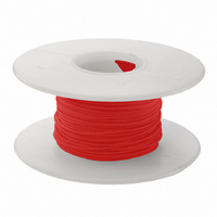
WIRE KYNAR INS 26AWG RED 100'
Manufacturer
OK Industries
Specifications of R26R-0100
Wire Gauge
26 AWG
Conductor Diameter
0.016" (0.40mm)
Length
100' (30.5m)
Jacket (insulation) Material
Kynar
Jacket (insulation) Diameter
0.027" (0.69mm)
Color
Red
Wire Size (awg)
26
Jacket Material
Polyvinylidene Fluoride (PVDF)
Maximum Temperature
+ 105 C
Wire Type
Wire Wrap
Application
Wire wrap
Color, Insulation
Red
Diameter, Outer, Nominal
0.0159 "
Material, Conductor
Silver-Coated Copper
Material, Insulation
Kynar
Standards
UL Listed
Stranding
Solid
Temperature, Rating
+105 °C
Temperature, Rating Uom Do Not Use
°C
Wire Size
26
Wire, Awg
26
Lead Free Status / RoHS Status
Lead free / RoHS Compliant
Lead Free Status / RoHS Status
Lead free / RoHS Compliant, Lead free / RoHS Compliant
Other names
K387


10
*These tools are recommended for .025" square terminals on .100” center to center of the pins
B I T S & S L E E V E S
Fully compatible with any make or model wire wrapping tool. Modified bits provide 1 1/2–2 turns of insulation.
Gauge
(AWG)
Wire
20-22
22-24
22-24
22-24
22-24
24-26
30-32
30-32
30-32
18
20
22
22
24
24
24
26
26
26
26
26
28
28
30
30
3 ”
INDUSTRIES CORP.
Regular
G
G
G
G
G
G
G
G
G
B I T S A N D S L E E V E S C H A R T
Modified
G
G
G
G
G
G
G
G
G
G
G
G
G
G
G
G
134 Marbledale Road, Tuckahoe, NY 10707
WB3032MIL †
SB30MSH-B*
WB2644M*
WB28SHM
SB30MMK*
WB3032M*
Part No.
WB2275M
WB24SM*
WB2426M
WB26SM*
WB2669M
WB2870M
WB20M
KB224LH
WB224M
WB24DH
KB224-1
WB26M
KB2075
KB3032
KB18
KB224
KB22
KB24
KB26
Bit
P3032LN
P3032LN
Part No.
P194LN
Sleeve
P194LN
P3032
P2224
P2224
P2224
P2224
P2224
P2224
P2224
P2224
P2426
P2224
P2426
P26LN
P2224
P2426
P2426
P3032
P3032
P3032
P3032
P3032
Maximum
Insulation
Diameter
Inches
†
.059
.030
.052
.050
.046
.044
.046
.031
.046
.046
.041
.034
.027
.023
.027
.027
Provides 2.5 turns of insulation
–
–
–
–
–
–
–
-
W I R E W R A P P I N G
(
Minimum
Diagonal
Terminal
Inches
A W G
.060
.031
.042
.042
.054
.049
.061
.054
.054
.049
.054
.055
.024
.054
.058
.023
.054
.024
.053
.053
.031
.031
.034
.034
.034
• www.jonard.com
)
Maximum
Diagonal
Terminal
Inches
.073
.035
.073
.073
.073
.074
.085
.073
.073
.074
.073
.074
.043
.073
.073
.038
.073
.043
.068
.068
.035
.035
.038
.038
.038
I N C H E S
Terminal
Depth
Inches
1.000
1.000
Hole
1.000
1.000
1.000
1.000
1.250
1.750
1.000
1.000
1.000
1.000
.750
.750
.807
.750
.750
.750
.750
.750
.750
.750
.750
.750
.750
Effective
.066
Radius
.123
.117
.132
.117
.111
.111
.121
.117
.100
.098
.118
.100
.075
.118
.098
.109
.103
.064
.064
.064
.064
.064
Inches
.150
.150
Diameter
Terminal
Inches
.075
Hole
.075
.036
.075
.040
.075
.075
.086
.075
.075
.075
.075
.075
.044
.075
.075
.040
.075
.044
.069
.070
.036
.036
.040
.040