MC14024BCPG ON Semiconductor, MC14024BCPG Datasheet
MC14024BCPG
Specifications of MC14024BCPG


Related parts for MC14024BCPG


MC14024BCPG Summary of contents
Page 1
MC14024B 7−Stage Ripple Counter The MC14024B is a 7−stage ripple counter with short propagation delays and high maximum clock rates. The Reset input has standard noise immunity, however the Clock input has increased noise immunity due to Hysteresis. The output ...
Page 2
... PIN PIN CONNECTION ORDERING INFORMATION Device MC14024BCP MC14024BCPG MC14024BD MC14024BDG MC14024BDR2 MC14024BDR2G MC14024BFEL MC14024BFELG †For information on tape and reel specifications, including part orientation and tape sizes, please refer to our Tape and Reel Packaging Specifications Brochure, BRD8011/D. TRUTH TABLE Clock Reset State ...
Page 3
ELECTRICAL CHARACTERISTICS Î Î Î Î Î ...
Page 4
SWITCHING CHARACTERISTICS (Note 5) Î Î Î ...
Page 5
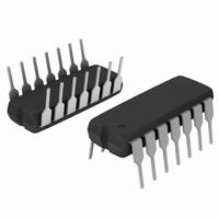
−T− SEATING PLANE 0.13 (0.005) PACKAGE DIMENSIONS PDIP−14 CASE 646−06 ISSUE NOTES: 1. DIMENSIONING AND TOLERANCING PER ANSI Y14.5M, ...