NC7SZ08L6X Fairchild Semiconductor, NC7SZ08L6X Datasheet - Page 5
NC7SZ08L6X
Manufacturer Part Number
NC7SZ08L6X
Description
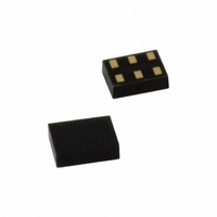
IC GATE AND UHS 2-INP 6-MICROPAK
Manufacturer
Fairchild Semiconductor
Series
7SZr
Datasheet
1.NC7SZ08P5X.pdf
(10 pages)
Specifications of NC7SZ08L6X
Logic Type
AND Gate
Number Of Inputs
2
Number Of Circuits
1
Current - Output High, Low
32mA, 32mA
Voltage - Supply
1.65 V ~ 5.5 V
Operating Temperature
-40°C ~ 85°C
Mounting Type
Surface Mount
Package / Case
6-MicroPak™
Product
AND
Logic Family
NC7SV
High Level Output Current
- 32 mA
Low Level Output Current
32 mA
Propagation Delay Time
5.2 ns
Supply Voltage (max)
5.5 V
Supply Voltage (min)
1.65 V
Maximum Operating Temperature
+ 85 C
Mounting Style
SMD/SMT
Minimum Operating Temperature
- 40 C
Logical Function
AND
Number Of Elements
1
Operating Supply Voltage (typ)
1.8/2.5/3.3/5V
Operating Temp Range
-40C to 85C
Package Type
MicroPak
Number Of Outputs
1
Technology
CMOS
Mounting
Surface Mount
Pin Count
6
Operating Temperature Classification
Industrial
Quiescent Current
2uA
Operating Supply Voltage (max)
5.5V
Operating Supply Voltage (min)
1.65V
Lead Free Status / RoHS Status
Lead free / RoHS Compliant
Available stocks
Company
Part Number
Manufacturer
Quantity
Price
Company:

Part Number:
NC7SZ08L6X
Manufacturer:
TI
Quantity:
25 000
Part Number:
NC7SZ08L6X
Manufacturer:
FAIRCHILD/ن»™ç«¥
Quantity:
20 000


© 1996 Fairchild Semiconductor Corporation
NC7SZ08 • Rev. 1.0.3
AC Electrical Characteristics
Note:
2.
Notes:
3.
4.
Note:
5.
Symbol
t
PLH
C
C
, t
PD
IN
C
current consumption (I
operating current by the expression: I
C
Input PRR=1.0MHz; t
Input=AC Waveform; t
PHL
PD
L
includes load and stray capacitance.
is defined as the value of the internal equivalent capacitance which is derived from dynamic operating
Propagation Delay
Input Capacitance
Power Dissipation
Capacitance
Parameter
Figure 4. AC Test Circuit
(2)
W
r
CCD
500ns.
=t
f
=1.8ns; PRR=10MHz; Duty Cycle=50%.
2.50 ± 0.20
3.30 ± 0.30
5.00 ± 0.50
3.30 ± 0.30
5.00 ± 0.50
) at no output lading and operating at 50% duty cycle. C
1.65
1.80
0.00
3.30
5.00
V
CC
CCD
C
R
C
R
Conditions
Figure 6. I
L
L
L
L
=(C
=15pF,
=1MΩ
=50pF,
=500Ω
PD
)(V
CC
)(f
CCD
5
IN
Min.
)+(I
Test Circuit
2.0
2.0
0.8
0.5
0.5
1.5
0.8
CC
T
static).
A
=25°C
Typ.
6.3
5.2
3.4
2.6
2.2
3.3
2.7
20
25
4
Figure 5. AC Waveforms
Max.
12.0
10.0
7.0
4.7
4.1
5.2
4.5
T
Min.
A
2.0
2.0
0.8
0.5
0.5
1.5
0.8
=-40 to +85°C
PD
is related to I
Max.
12.7
10.5
7.5
5.0
4.4
5.5
4.8
Units Figure
CCD
pF
pF
ns
www.fairchildsemi.com
dynamic
Figure 4
Figure 5
Figure 6
Related parts for NC7SZ08L6X
Image
Part Number
Description
Manufacturer
Datasheet
Request
R

Part Number:
Description:
Tinylogic Uhs 2-input And Gate
Manufacturer:
Fairchild Semiconductor
Datasheet:
Part Number:
Description:
Encoders, Decoders, Multiplexers & Demultiplexers Dec/Demultiplexer
Manufacturer:
Fairchild Semiconductor
Part Number:
Description:
Encoders, Decoders, Multiplexers & Demultiplexers 1-of-2 Dec/Demult
Manufacturer:
Fairchild Semiconductor
Part Number:
Description:
Encoders, Decoders, Multiplexers & Demultiplexers ULP 1 of 2 Decoder/Demultiplex
Manufacturer:
Fairchild Semiconductor
Part Number:
Description:
Fairchild Semiconductor [IGBT MODULE]
Manufacturer:
Fairchild Semiconductor
Datasheet:

Part Number:
Description:
Discrete Semiconductor Modules
Manufacturer:
Fairchild Semiconductor
Part Number:
Description:
Discrete Semiconductor Modules
Manufacturer:
Fairchild Semiconductor
Part Number:
Description:
This N-Channel MOSFET is produced using Fairchild Semiconductor’s advanced Power Trench® process
Manufacturer:
Fairchild Semiconductor
Datasheet:
Part Number:
Description:
This N-Channel MOSFET is produced using Fairchild Semiconductor’s advanced Power Trench® process
Manufacturer:
Fairchild Semiconductor
Datasheet:
Part Number:
Description:
This N-Channel MOSFET is produced using Fairchild Semiconductor’s advanced PowerTrench® process
Manufacturer:
Fairchild Semiconductor
Datasheet:
Part Number:
Description:
This N-Channel MOSFET is produced using Fairchild Semiconductor’s advanced PowerTrench® process
Manufacturer:
Fairchild Semiconductor
Datasheet:
Part Number:
Description:
This N-Channel MOSFET is produced using Fairchild Semiconductor’s advanced Power Trench® process
Manufacturer:
Fairchild Semiconductor
Datasheet:
Part Number:
Description:
This N-Channel logic Level MOSFETs are produced using Fairchild Semiconductor‘s advanced Power Trench® process that has been special tailored to minimize the on-state resistance and yet maintain superior switching performance
Manufacturer:
Fairchild Semiconductor
Datasheet:
Part Number:
Description:
This N-Channel MOSFET is produced using Fairchild Semiconductor’s advanced Power Trench® process
Manufacturer:
Fairchild Semiconductor
Datasheet:
Part Number:
Description:
This N-Channel SyncFET™ is produced using Fairchild Semiconductor’s advanced PowerTrench® process
Manufacturer:
Fairchild Semiconductor
Datasheet: