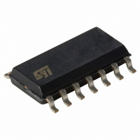
74LVC14AMTR STMicroelectronics, 74LVC14AMTR Datasheet - Page 5

74LVC14AMTR
Manufacturer Part Number
74LVC14AMTR
Description
IC HEX INVERTER LV 14-SOIC
Manufacturer
STMicroelectronics
Series
74LVCr
Datasheet
1.74LVC14ATTR.pdf
(12 pages)
Specifications of 74LVC14AMTR
Logic Type
Inverter
Number Of Inputs
1
Number Of Circuits
6
Current - Output High, Low
24mA, 24mA
Voltage - Supply
1.65 V ~ 3.6 V
Operating Temperature
-55°C ~ 125°C
Mounting Type
Surface Mount
Package / Case
14-SOIC (3.9mm Width), 14-SOL
Lead Free Status / RoHS Status
Contains lead / RoHS non-compliant
Other names
497-1074-2
Available stocks
Company
Part Number
Manufacturer
Quantity
Price
Table 8: AC Electrical Characteristics
1) Skew is defined as the absolute value of the difference between the actual propagation delay for any two outputs of the same device switch-
ing in the same direction, either HIGH or LOW (t
2) Parameter guaranteed by design
Table 9: Capacitive Characteristics
1) C
load. (Refer to Test Circuit). Average operating current can be obtained by the following equation. I
t
Symbol
Symbol
PLH
t
t
PD
OSLH
OSHL
C
C
PD
is defined as the value of the IC’s internal equivalent capacitance which is calculated from the operating current consumption without
IN
t
PHL
Propagation Delay
Time
Output To Output
Skew Time (note1,
2)
Input Capacitance
Power Dissipation Capacitance
(note 1)
Parameter
Parameter
1.65 to 1.95
2.3 to 2.7
3.0 to 3.6
2.7 to 3.6
V
(V)
2.7
CC
OSLH
Test Condition
= | t
PLHm
(pF)
V
C
30
30
50
50
(V)
1.8
2.5
3.3
CC
L
- t
PLHn
Test Condition
1000
500
500
500
( )
R
|, t
L
OSHL
t
f
s
(ns)
IN
2.0
2.0
2.5
2.5
= | t
= t
= 10MHz
r
PHLm
Min.
- t
-40 to 85 °C
1
PHLn
|
CC(opr)
Max.
10.5
7.0
6.0
5.0
Min.
1
Value
= C
T
PD
A
Min.
Value
-55 to 125 °C
= 25 °C
Typ.
x V
1
37
38
42
4
CC
x f
IN
Max.
Max.
+ I
9.1
7.5
6.4
14
1
74LVC14A
CC
/n (per circuit)
Unit
Unit
pF
pF
ns
ns
5/12


