MC74HCT04ANG ON Semiconductor, MC74HCT04ANG Datasheet - Page 7
MC74HCT04ANG
Manufacturer Part Number
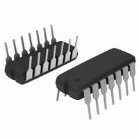
MC74HCT04ANG
Description
IC INVERTER HEX LSTTL IN 14-DIP
Manufacturer
ON Semiconductor
Series
74HCTr
Specifications of MC74HCT04ANG
Logic Type
Inverter
Number Of Inputs
1
Number Of Circuits
6
Current - Output High, Low
4mA, 4mA
Voltage - Supply
4.5 V ~ 5.5 V
Operating Temperature
-55°C ~ 125°C
Mounting Type
Through Hole
Package / Case
14-DIP (0.300", 7.62mm)
Circuit Type
Low-Power Schottky
Current, Supply
40 μA
Function Type
6-Channels
Logic Function
Inverter
Package Type
PDIP-14
Temperature, Operating, Range
-55 to +125 °C
Voltage, Supply
4.5 to 5.5 V
Output Current
4mA
No. Of Inputs
1
Supply Voltage Range
4.5V To 5.5V
Logic Case Style
DIP
No. Of Pins
14
Operating Temperature Range
-55°C To +125°C
Filter Terminals
DIP
Rohs Compliant
Yes
Family Type
HCT
Lead Free Status / RoHS Status
Lead free / RoHS Compliant
Other names
MC74HCT04ANGOS


−T−
0.15 (0.006) T
0.15 (0.006) T
0.10 (0.004)
SEATING
PLANE
L
U
U
PIN 1
IDENT.
2X
D
S
S
L/2
C
14
1
0.36
G
14X
14X
*For additional information on our Pb−Free strategy and soldering
−V−
A
details, please download the ON Semiconductor Soldering and
Mounting Techniques Reference Manual, SOLDERRM/D.
K
0.10 (0.004)
REF
8
7
SOLDERING FOOTPRINT*
M
−U−
PACKAGE DIMENSIONS
1
B
T
H
1.26
14X
U
http://onsemi.com
J J1
N
CASE 948G−01
S
N
TSSOP−14
DETAIL E
ISSUE B
V
7.06
S
DETAIL E
7
SECTION N−N
Ç Ç Ç
Ç Ç Ç
É É É
Ç Ç Ç
É É É
F
K1
K
0.25 (0.010)
M
DIMENSIONS: MILLIMETERS
−W−
NOTES:
0.65
PITCH
1. DIMENSIONING AND TOLERANCING PER
2. CONTROLLING DIMENSION: MILLIMETER.
3. DIMENSION A DOES NOT INCLUDE MOLD
4. DIMENSION B DOES NOT INCLUDE
5. DIMENSION K DOES NOT INCLUDE
6. TERMINAL NUMBERS ARE SHOWN FOR
7. DIMENSION A AND B ARE TO BE
ANSI Y14.5M, 1982.
FLASH, PROTRUSIONS OR GATE BURRS.
MOLD FLASH OR GATE BURRS SHALL NOT
EXCEED 0.15 (0.006) PER SIDE.
INTERLEAD FLASH OR PROTRUSION.
INTERLEAD FLASH OR PROTRUSION SHALL
NOT EXCEED 0.25 (0.010) PER SIDE.
DAMBAR PROTRUSION. ALLOWABLE
DAMBAR PROTRUSION SHALL BE 0.08
(0.003) TOTAL IN EXCESS OF THE K
DIMENSION AT MAXIMUM MATERIAL
CONDITION.
REFERENCE ONLY.
DETERMINED AT DATUM PLANE −W−.
DIM
K1
J1
A
B
C
D
G
H
K
M
F
J
L
MILLIMETERS
MIN
4.90
4.30
0.05
0.50
0.50
0.09
0.09
0.19
0.19
−−−
0
0.65 BSC
6.40 BSC
_
MAX
5.10 0.193
4.50 0.169
1.20
0.15 0.002
0.75 0.020
0.60 0.020
0.20 0.004
0.16 0.004
0.30 0.007
0.25 0.007
8
_
MIN
−−− 0.047
0.026 BSC
0.252 BSC
0
INCHES
_
0.200
0.177
0.006
0.030
0.024
0.008
0.006
0.012
0.010
MAX
8
_
Related parts for MC74HCT04ANG
Image
Part Number
Description
Manufacturer
Datasheet
Request
R

Part Number:
Description:
ON Semiconductor [VOLTAGE REGULATOR]
Manufacturer:
ON Semiconductor
Datasheet:
Part Number:
Description:
357-036-542-201 CARDEDGE 36POS DL .156 BLK LOPRO
Manufacturer:
ON Semiconductor
Datasheet:
Part Number:
Description:
357-036-542-201 CARDEDGE 36POS DL .156 BLK LOPRO
Manufacturer:
ON Semiconductor
Datasheet:
Part Number:
Description:
357-036-542-201 CARDEDGE 36POS DL .156 BLK LOPRO
Manufacturer:
ON Semiconductor
Datasheet:
Part Number:
Description:
357-036-542-201 CARDEDGE 36POS DL .156 BLK LOPRO
Manufacturer:
ON Semiconductor
Datasheet:
Part Number:
Description:
357-036-542-201 CARDEDGE 36POS DL .156 BLK LOPRO
Manufacturer:
ON Semiconductor
Datasheet:
Part Number:
Description:
357-036-542-201 CARDEDGE 36POS DL .156 BLK LOPRO
Manufacturer:
ON Semiconductor
Datasheet:
Part Number:
Description:
357-036-542-201 CARDEDGE 36POS DL .156 BLK LOPRO
Manufacturer:
ON Semiconductor
Datasheet:
Part Number:
Description:
357-036-542-201 CARDEDGE 36POS DL .156 BLK LOPRO
Manufacturer:
ON Semiconductor
Datasheet:
Part Number:
Description:
357-036-542-201 CARDEDGE 36POS DL .156 BLK LOPRO
Manufacturer:
ON Semiconductor
Datasheet:
Part Number:
Description:
357-036-542-201 CARDEDGE 36POS DL .156 BLK LOPRO
Manufacturer:
ON Semiconductor
Datasheet:
Part Number:
Description:
Manufacturer:
ON Semiconductor
Datasheet:
Part Number:
Description:
Manufacturer:
ON Semiconductor
Datasheet:
Part Number:
Description:
Manufacturer:
ON Semiconductor
Datasheet: