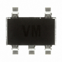
74LX1G04STR STMicroelectronics, 74LX1G04STR Datasheet

74LX1G04STR
Specifications of 74LX1G04STR
Available stocks
Related parts for 74LX1G04STR
74LX1G04STR Summary of contents
Page 1
... It can be interfaced to 5V signal environment for inputs in mixed 3.3/5V system. All inputs and outputs are equipped with protection circuits against static discharge. 74LX1G04 SOT23-5 SOT323-5 Flip-Chip4 PACKAGE T & R SOT23-5L 74LX1G04STR SOT323-5L 74LX1G04CTR Flip-Chip 74LX1G04BJR 1/13 ...
Page 2
INPUT AND OUTPUT EQUIVALENT CIRCUIT PIN DESCRIPTION PIN for SOT PIN for Flip-Chip TRUTH TABLE ABSOLUTE MAXIMUM RATINGS Symbol V Supply Voltage Input Voltage ...
Page 3
RECOMMENDED OPERATING CONDITIONS Symbol V Supply Voltage (note Input Voltage I V Output Voltage ( Output Voltage (High or Low State High or Low Level Output Current ( ...
Page 4
AC ELECTRICAL CHARACTERISTICS Symbol Parameter t t Propagation Delay PLH PHL Time CAPACITANCE CHARACTERISTICS Symbol Parameter C Input Capacitance IN C Power Dissipation Capacitance PD (note defined as the value of the IC’s internal equivalent ...
Page 5
TEST CIRCUIT pulse generator (typically OUT TEST CIRCUIT AND WAVEFORM SYMBOL VALUE Symbol WAVEFORM: PROPAGATION DELAY (f=1MHz; 50% duty cycle) ...
Page 6
... For Flip-Chip mounting on the PCB, STMicroelectronics recommends the use of a solder stencil aperture of 330 x 330 µm² maximum and a typical stencil thickness of 125µm. Flip-Chips are fully compatible with the use of near eutectic 95.5Sn 4Ag 0.5Cu solder paste with no clean flux. ST's recommendations for Flip-Chip board mounting are illustrated on the soldering reflow profile shown in figure 1 below. Dwell time in the soldering zone (with temperature higher than 220° ...
Page 7
SOT23-5L MECHANICAL DATA DIM. MIN. A 0.90 A1 0.00 A2 0.90 b 0.35 C 0.09 D 2. 2.60 L 0.10 mm. TYP MAX. MIN. 1.45 0.10 1.30 0.50 0.20 3.00 110.2 1.75 0.95 3.00 102.3 0.60 ...
Page 8
DIM. MIN. A 0.80 A1 0.00 A2 0.80 b 0.15 C 0.10 D 1.80 E 1. 0.10 8/13 SOT323-5L MECHANICAL DATA mm. TYP MAX. 1.10 0.10 1.00 0.30 0.18 2.20 2.40 1.35 .65 0 ...
Page 9
Flip-Chip4 MECHANICAL DATA DIM. MIN. A 0.585 A1 0. 0.265 0.315 D 1. 1.02 E1 mm. TYP MAX. MIN. 0.65 0.715 23.03 0.25 0.29 0.40 0.365 10.43 1.07 1.12 40.15 0.5 1.07 1.12 40.15 0.5 74LX1G04 ...
Page 10
Tape & Reel SOT23-xL MECHANICAL DATA DIM. MIN 12 3.13 Bo 3.07 Ko 1.27 Po 3.9 P 3.9 10/13 mm. TYP MAX. MIN. 180 13.0 13.2 0.504 0.795 2.362 14.4 3.23 ...
Page 11
Tape & Reel SOT323-xL MECHANICAL DATA DIM. MIN. A 175 C 12.8 D 20 3.9 P 3.8 mm. TYP MAX. MIN. 180 185 6.889 13 13.2 0.504 0.795 60 60.5 14.4 2.25 2.7 ...
Page 12
Tape & Reel Flip-Chip 4 MECHANICAL DATA DIM. MIN 12 1.12 Bo 1.12 Ko 0.68 Po 3.9 P 3.9 12/13 mm. TYP MAX. MIN. 178 13.2 0.504 0.795 60 61 2.323 ...
Page 13
... No license is granted by implication or otherwise under any patent or patent rights of STMicroelectronics. Specifications mentioned in this publication are subject to change without notice. This publication supersedes and replaces all information previously supplied ...


