NL7SZ97DFT2G ON Semiconductor, NL7SZ97DFT2G Datasheet - Page 7
NL7SZ97DFT2G
Manufacturer Part Number
NL7SZ97DFT2G
Description
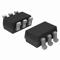
IC GATE MULTIFUNCT CONF SC-88
Manufacturer
ON Semiconductor
Series
7SZr
Datasheet
1.NL7SZ97DFT2G.pdf
(8 pages)
Specifications of NL7SZ97DFT2G
Logic Type
Configurable Multiple Function
Number Of Circuits
1
Number Of Inputs
3
Schmitt Trigger Input
Yes
Output Type
Single-Ended
Current - Output High, Low
32mA, 32mA
Voltage - Supply
1.65 V ~ 5.5 V
Operating Temperature
-55°C ~ 125°C
Mounting Type
Surface Mount
Package / Case
SC-70-6, SC-88, SOT-363
Product
MUX Gates
Logic Family
LCX
High Level Output Current
- 32 mA
Low Level Output Current
32 mA
Propagation Delay Time
6.3 ns
Supply Voltage (max)
5.5 V
Supply Voltage (min)
1.65 V
Maximum Operating Temperature
+ 125 C
Mounting Style
SMD/SMT
Minimum Operating Temperature
- 55 C
Lead Free Status / RoHS Status
Lead free / RoHS Compliant
Other names
NL7SZ97DFT2G
NL7SZ97DFT2GOSTR
NL7SZ97DFT2GOSTR
Available stocks
Company
Part Number
Manufacturer
Quantity
Price
Company:

Part Number:
NL7SZ97DFT2G
Manufacturer:
ON
Quantity:
12 000
Company:
Part Number:
NL7SZ97DFT2G
Manufacturer:
ON Semiconductor
Quantity:
1 250
Part Number:
NL7SZ97DFT2G
Manufacturer:
ON/安森美
Quantity:
20 000


†For information on tape and reel specifications, including part orientation and tape sizes, please refer to our Tape and Reel Packaging
8. Waveform 1 is for an output with internal conditions such that the output is low, except when disabled by the output control.
9. Waveform 2 is for an output with internal conditions such that the output is high, except when disabled by the output control
10. All input pulses are supplied by generators having the following characteristics: PRR v 10 MHz, Z
11. The outputs are measured one at a time, with one transition per measurement.
12. All parameters are waveforms are not applicable to all devices.
ORDERING INFORMATION
NL7SZ97DFT2G
Specifications Brochure, BRD8011/D.
Figure 12. Voltage Waveforms Propagation Delay
Figure 10. Voltage Waveforms Pulse Duration
Input
Times Inverting and Noninverting Outputs
Output
Output
Input
t
t
PLH
PHL
Device
V
V
M
M
t
W
V
V
M
M
V
M
t
t
V
PHL
PLH
V
V
M
M
M
V
0 V
V
V
V
V
I
OH
OL
OH
OL
V
0 V
I
http://onsemi.com
(Pb−Free)
Package
SC−88
7
S1 at V
Waveform 1
Waveform 2
S1 at GND
Timing Input
Data Input
(Note 8)
(Note 9)
Figure 11. Voltage Waveforms Setup and Hold
Disable Times Low− and High−Level Enabling
Control
Output
Output
Output
Figure 13. Voltage Waveforms Enable and
LOAD
t
PZH
V
M
t
su
V
V
V
M
Times
M
M
O
= 50 W.
V
t
M
h
3000 / Tape & Reel
V
M
Shipping
V
V
OL
OH
V
t
PHZ
M
+ V
− V
V
0 V
D
V
V
V
D
[0 V
I
†
V
0 V
V
0 V
LOAD
OL
OH
I
I
/2
Related parts for NL7SZ97DFT2G
Image
Part Number
Description
Manufacturer
Datasheet
Request
R

Part Number:
Description:
Flexible Choice Logic 9 Functions
Manufacturer:
ON Semiconductor
Datasheet:
Part Number:
Description:
ON Semiconductor [VOLTAGE REGULATOR]
Manufacturer:
ON Semiconductor
Datasheet:
Part Number:
Description:
357-036-542-201 CARDEDGE 36POS DL .156 BLK LOPRO
Manufacturer:
ON Semiconductor
Datasheet:
Part Number:
Description:
357-036-542-201 CARDEDGE 36POS DL .156 BLK LOPRO
Manufacturer:
ON Semiconductor
Datasheet:
Part Number:
Description:
357-036-542-201 CARDEDGE 36POS DL .156 BLK LOPRO
Manufacturer:
ON Semiconductor
Datasheet:
Part Number:
Description:
357-036-542-201 CARDEDGE 36POS DL .156 BLK LOPRO
Manufacturer:
ON Semiconductor
Datasheet:
Part Number:
Description:
357-036-542-201 CARDEDGE 36POS DL .156 BLK LOPRO
Manufacturer:
ON Semiconductor
Datasheet:
Part Number:
Description:
357-036-542-201 CARDEDGE 36POS DL .156 BLK LOPRO
Manufacturer:
ON Semiconductor
Datasheet:
Part Number:
Description:
357-036-542-201 CARDEDGE 36POS DL .156 BLK LOPRO
Manufacturer:
ON Semiconductor
Datasheet:
Part Number:
Description:
357-036-542-201 CARDEDGE 36POS DL .156 BLK LOPRO
Manufacturer:
ON Semiconductor
Datasheet:
Part Number:
Description:
357-036-542-201 CARDEDGE 36POS DL .156 BLK LOPRO
Manufacturer:
ON Semiconductor
Datasheet:
Part Number:
Description:
357-036-542-201 CARDEDGE 36POS DL .156 BLK LOPRO
Manufacturer:
ON Semiconductor
Datasheet:
Part Number:
Description:
Manufacturer:
ON Semiconductor
Datasheet:
Part Number:
Description:
Manufacturer:
ON Semiconductor
Datasheet: