DM74LS221N Fairchild Semiconductor, DM74LS221N Datasheet - Page 2
DM74LS221N
Manufacturer Part Number
DM74LS221N
Description
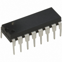
IC ONE-SHOT DL NON-RETRIG 16-DIP
Manufacturer
Fairchild Semiconductor
Series
74LSr
Datasheet
1.DM74LS221N.pdf
(8 pages)
Specifications of DM74LS221N
Logic Type
Monostable
Independent Circuits
2
Schmitt Trigger Input
Yes
Propagation Delay
65ns
Current - Output High, Low
400µA, 8mA
Voltage - Supply
4.75 V ~ 5.25 V
Operating Temperature
0°C ~ 70°C
Mounting Type
Through Hole
Package / Case
16-DIP (0.300", 7.62mm)
Lead Free Status / RoHS Status
Contains lead / RoHS non-compliant
Other names
74LS221
74LS221N
74LS221N
Available stocks
Company
Part Number
Manufacturer
Quantity
Price
Company:

Part Number:
DM74LS221N
Manufacturer:
01+
Quantity:
750
Part Number:
DM74LS221N
Manufacturer:
NS/ه›½هچٹ
Quantity:
20 000
Company:
Part Number:
DM74LS221N*
Manufacturer:
national
Quantity:
500


www.fairchildsemi.com
Functional Description
The basic output pulse width is determined by selection of
an external resistor (R
gered, the basic pulse width is independent of further input
transitions and is a function of the timing components, or it
Operating Rules
1.
2.
3.
4.
5. For C
6.
7.
(C
may vary from 0 to approximately 1000 F. For small
time constants high-grade mica, glass, polypropylene,
polycarbonate, or polystyrene material capacitor may
be used. For large time constants use tantalum or spe-
cial aluminum capacitors. If timing capacitor has leak-
ages approaching 100 nA or if stray capacitance from
either terminal to ground is greater than 50 pF the tim-
ing equations may not represent the pulse width the
device generates.
ing diode is often required for standard TTL one-shots
to prevent high inverse leakage current. This switching
diode is not needed for the DM74LS221 one-shot and
should not be used.
Furthermore, if a polarized timing capacitor is used on
the DM74LS221, the positive side of the capacitor
should be connected to the “C
defined as follows:
t
where [R
for design considerations: (See Figure 4).
curves with R
the following circuit is recommended: (See Figure 2).
ure 5 depicts the relationship between pulse width vari-
ation versus V
versus temperatures.
The multiplicative factor K is plotted as a function of C
When an electrolytic capacitor is used for C
W
Output pulse width versus V
An external resistor (R
For C
To obtain variable pulse widths by remote trimming,
X
) are required for proper operation. The value of C
KR
X
[C
[t
K
X
X
W
X
X
C
is in ns]
1000 pF see Figure 3 for t
Ln2
is in k ]
is in pF]
X
1000 pF, the output pulse width (t
X
CC
as a parameter.
. Figure 6 depicts pulse width variation
0.70
X
) and capacitor (C
X
) and an external capacitor
CC
EXT
and temperatures: Fig-
” pin (Figure 1).
W
X
vs. C
). Once trig-
X
a switch-
X
family
W
) is
X
X
2
may be reduced or terminated by use of the active low
CLEAR input. Stable output pulse width ranging from 30 ns
to 70 seconds is readily obtainable.
8. Duty cycle is defined as t
9. Under any operating condition C
10. Although the DM74LS221's pin-out is identical to the
11. V
goes above 50% the output pulse width will become
shorter. If the duty cycle varies between LOW and
HIGH values, this causes output pulse width to vary, or
jitter (a function of the R
should be as large as possible, for example, with
R
approaches 90%.
as close to the one-shot device pins as possible to min-
imize stray capacitance, to reduce noise pick-up, and
to reduce I-R and Ldi/dt voltage developed along their
connecting paths. If the lead length from C
and (7) or pins (14) and (15) is greater than 3 cm, for
example, the output pulse width might be quite different
from values predicted from the appropriate equations.
A non-inductive and low capacitive path is necessary to
ensure complete discharge of C
operation so that the output pulse width will be accu-
rate.
DM74LS123 it should be remembered that they are not
functionally identical. The DM74LS123 is a retrigger-
able device such that the output is dependent upon the
input transitions when its output “Q” is at the “High”
state. Furthermore, it is recommended for the
DM74LS123 to externally ground the C
improved system performance. However, this pin on
the DM74LS221 is not an internal connection to the
device ground. Hence, if substitution of an DM74LS221
onto an DM74LS123 design layout where the C
is wired to the ground, the device will not function.
frequency standards and practices so that switching
transients on the V
cause interaction between one-shots. A 0.01 F to 0.10
from V
thermore, the bypass capacitor should be located as
close to the V
F bypass capacitor (disk ceramic or monolithic type)
EXT
CC
and ground wiring should conform to good high-
CC
100k jitter is not appreciable until the duty cycle
to ground is necessary on each device. Fur-
CC
-pin as space permits.
CC
and ground return leads do not
EXT
W
/T
only). To reduce jitter, R
100 in percentage, if it
X
X
and R
in each cycle of its
X
must be kept
X
EXT
to pins (6)
EXT
pin for
EXT
pin
Related parts for DM74LS221N
Image
Part Number
Description
Manufacturer
Datasheet
Request
R

Part Number:
Description:
Hex Inverters with Schmitt Trigger Inputs
Manufacturer:
National Semiconductor
Datasheet:

Part Number:
Description:
Fairchild Semiconductor [IGBT MODULE]
Manufacturer:
Fairchild Semiconductor
Datasheet:

Part Number:
Description:
Discrete Semiconductor Modules
Manufacturer:
Fairchild Semiconductor
Part Number:
Description:
Discrete Semiconductor Modules
Manufacturer:
Fairchild Semiconductor
Part Number:
Description:
This N-Channel MOSFET is produced using Fairchild Semiconductor’s advanced Power Trench® process
Manufacturer:
Fairchild Semiconductor
Datasheet:
Part Number:
Description:
This N-Channel MOSFET is produced using Fairchild Semiconductor’s advanced Power Trench® process
Manufacturer:
Fairchild Semiconductor
Datasheet:
Part Number:
Description:
This N-Channel MOSFET is produced using Fairchild Semiconductor’s advanced PowerTrench® process
Manufacturer:
Fairchild Semiconductor
Datasheet:
Part Number:
Description:
This N-Channel MOSFET is produced using Fairchild Semiconductor’s advanced PowerTrench® process
Manufacturer:
Fairchild Semiconductor
Datasheet:
Part Number:
Description:
This N-Channel MOSFET is produced using Fairchild Semiconductor’s advanced Power Trench® process
Manufacturer:
Fairchild Semiconductor
Datasheet:
Part Number:
Description:
This N-Channel logic Level MOSFETs are produced using Fairchild Semiconductor‘s advanced Power Trench® process that has been special tailored to minimize the on-state resistance and yet maintain superior switching performance
Manufacturer:
Fairchild Semiconductor
Datasheet:
Part Number:
Description:
This N-Channel MOSFET is produced using Fairchild Semiconductor’s advanced Power Trench® process
Manufacturer:
Fairchild Semiconductor
Datasheet:
Part Number:
Description:
This N-Channel SyncFET™ is produced using Fairchild Semiconductor’s advanced PowerTrench® process
Manufacturer:
Fairchild Semiconductor
Datasheet:
Part Number:
Description:
This N-Channel SyncFET™ is produced using Fairchild Semiconductor’s advanced PowerTrench® process
Manufacturer:
Fairchild Semiconductor
Datasheet:
Part Number:
Description:
This N-Channel SyncFET™ is produced using Fairchild Semiconductor’s advanced PowerTrench® process
Manufacturer:
Fairchild Semiconductor
Datasheet: