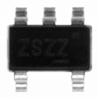
PI5C3301TEX Pericom Semiconductor, PI5C3301TEX Datasheet - Page 3

PI5C3301TEX
Manufacturer Part Number
PI5C3301TEX
Description
IC 1-BIT BUS SWITCH SOT23-5
Manufacturer
Pericom Semiconductor
Type
Bus Switchr
Datasheet
1.PI5C3301TEX.pdf
(5 pages)
Specifications of PI5C3301TEX
Circuit
1 x 1:1
Independent Circuits
1
Voltage Supply Source
Single Supply
Voltage - Supply
4 V ~ 5.5 V
Operating Temperature
-40°C ~ 85°C
Mounting Type
Surface Mount
Package / Case
SOT-23-5, SC-74A, SOT-25
Lead Free Status / RoHS Status
Lead free / RoHS Compliant
Current - Output High, Low
-
Other names
PI5C3301TEX
PI5C3301TEXTR
PI5C3301TEXTR
Available stocks
Company
Part Number
Manufacturer
Quantity
Price
Part Number:
PI5C3301TEX
Manufacturer:
PERICOM
Quantity:
20 000
1 2 3 4 5 6 7 8 9 0 1 2 3 4 5 6 7 8 9 0 1 2 3 4 5 6 7 8 9 0 1 2 1 2 3 4 5 6 7 8 9 0 1 2 3 4 5 6 7 8 9 0 1 2 3 4 5 6 7 8 9 0 1 2 1 2 3 4 5 6 7 8 9 0 1 2 3 4 5 6 7 8 9 0 1 2 3 4 5 6 7 8 9 0 1 2 1 2 3 4 5 6 7 8 9 0 1 2 3 4 5 6 7 8 9 0 1 2 3 4 5 6 7 8 9 0 1 2 1 2 3 4 5 6 7 8 9 0 1 2
1 2 3 4 5 6 7 8 9 0 1 2 3 4 5 6 7 8 9 0 1 2 3 4 5 6 7 8 9 0 1 2 1 2 3 4 5 6 7 8 9 0 1 2 3 4 5 6 7 8 9 0 1 2 3 4 5 6 7 8 9 0 1 2 1 2 3 4 5 6 7 8 9 0 1 2 3 4 5 6 7 8 9 0 1 2 3 4 5 6 7 8 9 0 1 2 1 2 3 4 5 6 7 8 9 0 1 2 3 4 5 6 7 8 9 0 1 2 3 4 5 6 7 8 9 0 1 2 1 2 3 4 5 6 7 8 9 0 1 2
Notes:
1. For Max. or Min. conditions, use appropriate value specified under Electrical Characteristics for the applicable device.
2. Typical values are at V
3. Per TTL driven input (V
Switching Characteristics over Operating Range
Notes:
1. This parameter is guaranteed but not tested on Propagation Delays.
2. The bus switch contributes no propagational delay other than the RC delay of the On-Resistance of the switch and the load capacitance. The
Power Supply Characteristics
P
time constant for the switch alone is of the order of 0.25ns for 50pF load. Since his time constant is much smaller than the rise/fall times of
typical driving signals, it adds very little propagational delay to the system. Propagational delay of the bus switch when used in a system is
determined by the driving circuit on the driving side of the switch and its interaction with the load on the driven side.
a
P
a r
a
I
C
I
m
a r
C
09-0002
C
t
t
t
t
t
t
e
P
P
P
P
C
P
P
m
L
H
Z
H
e t
Z
L
H
H
e
L
Z
L
Z
s r
e t
s r
Q
S
u
u
p p
s e i
y l
e c
r P
A
B
B
CC
C
t n
s u
s u
p o
o t
IN
r u
P
= 5.0V, +25°C ambient.
E
D
g a
e r
, B
= 3.4V, control inputs only); A and B pins do not contribute to I
o
n
s i
w
t n
b a
i t a
b a
D
B
r e
e p
n o
D
e l
e
e l
o t
c s
S
e
I r
T
T
D
u
c s
m i
A
i r
m i
p p
p n
l e
i r
t p
e
y a
e
y l
t u
t p
o i
(
o i
C
, 1
n
@
) 2
r u
n
T
e r
T
t n
L
H
G I
H
V
V
R
C
C
L
C
C
C
C
=
o
L
=
=
n
=
0 5
d
M
M
3
t i
5
- 0
a
a
o i
p 0
e T
. x
. x
h o
s n
F
t s
m
C
V
V
o
N I
N I
n
d
=
=
t i
o i
M
G
3
1
1
s n
4 .
N
V
0 .
0 .
. n i
V
C
(
D
) 1
C
(
) 3
r o
CC
=
.
V
4
5 .
M
C
. 0
4
4
C
V
a
9 .
2 .
5 2
SOTiny
P
. x
5 I
C
M
3 3
. n i
M
1 0
TM
. n i
V
Single-Bit Bus Switch
T
C
y
0
C
. p
1 .
=
(
) 2
4
M
. 0
V
4
5
a
5 .
5 2
5 .
M
. x
PS8366I
3
2
a
0 .
5 .
. x
PI5C3301
U
U
n
s n
m
μ
10/29/09
n
s t i
A
A
s t i


