SY89840UMG TR Micrel Inc, SY89840UMG TR Datasheet - Page 7
SY89840UMG TR
Manufacturer Part Number
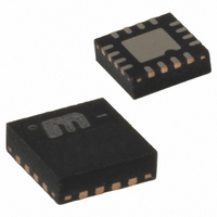
SY89840UMG TR
Description
IC MUX 2:1 LVPECL RPE/FSI 16MLF
Manufacturer
Micrel Inc
Series
SY89r
Type
Multiplexerr
Datasheet
1.SY89840UMG.pdf
(15 pages)
Specifications of SY89840UMG TR
Circuit
1 x 2:1
Independent Circuits
1
Voltage Supply Source
Single Supply
Voltage - Supply
3 V ~ 3.6 V
Operating Temperature
-40°C ~ 85°C
Mounting Type
Surface Mount
Package / Case
16-MLF®, QFN
Lead Free Status / RoHS Status
Lead free / RoHS Compliant
Current - Output High, Low
-
Other names
SY89840UMGTR
SY89840UMGTR
SY89840UMGTR


February 2005
AC Electrical Characteristics
V
Notes:
7.
8.
9.
10. Random jitter is measured with a K28.7 character pattern, measured at <f
11. Cycle-to-cycle jitter definition: The variation of periods between adjacent cycles, T
12. Total jitter definition: with an ideal clock input of frequency <f
13. Crosstalk is measured at the output while applying two similar differential clock frequencies that are asynchronous with respect to each
Symbol
f
t
t
Tempco
t
t
t
CC
MAX
pd
pd
SKEW
Jitter
r,
t
f
High-frequency AC-parameters are guaranteed by design and characterization.
Propagation delay is measured with input t
Part-to-part skew is defined for two parts with identical power supply voltages at the same temperature and with no skew of the edges at
the respective inputs.
output signal.
than the specified peak-to-peak jitter value.
other at the inputs.
= 2.5V ±5% or 3.3V ±10%; T
Parameter
Maximum Operating Frequency
Differential Propagation Delay In-to-Q
Differential Propagation Delay
Temperature Coefficient
Part-to-Part Skew
Crosstalk-induced Jitter
Output Rise/Fall Time (20% to 80%)
Cycle-to-Cycle Jitter
A
Total Jitter (TJ)
Random Jitter
= –40°C to + 85°C, R
SEL-to-Q
SEL-to-Q
r
, t
f
(7)
In-to-Q
≤ 300ps (20% to 80%) and V
Condition
Clock
100mV < V
200mV < V
RPE enabled, see Timing Diagram
RPE disabled (V
Note 9
Note 10
Note 11
Note 12
Note 13
At full output swing
MAX
, no more than one output edge in 10
L
= 50Ω to V
IN
IN
7
≤ 200mV
≤ 800mV
MAX
IL
IN
≥ 800mV.
.
= V
CC
(8)
(8)
n
CC
–2V, unless otherwise stated.
– T
/2)
n-1
where T is the time between rising edges of the
hbwhelp@micrel.com
12
Min
480
460
550
1.5
output edges will deviate by more
70
Typ
625
600
115
130
2.0
or (408) 955-1690
Max
880
820
900
200
190
0.7
17
10
1
1
M9999-021705
cycles
ps
ps
ps
Units
ps
fs/
GHz
ps
ps
ps
ps
ps
(rms)
(rms)
(rms)
(pp)
o
C
Related parts for SY89840UMG TR
Image
Part Number
Description
Manufacturer
Datasheet
Request
R

Part Number:
Description:
Manufacturer:
Micrel Inc
Datasheet:
Part Number:
Description:
Manufacturer:
Micrel Inc
Datasheet:
Part Number:
Description:
Manufacturer:
Micrel Inc
Datasheet:
Part Number:
Description:
Manufacturer:
Micrel Inc
Datasheet:
Part Number:
Description:
Manufacturer:
Micrel Inc
Datasheet:
Part Number:
Description:
Manufacturer:
Micrel Inc
Datasheet:
Part Number:
Description:
Manufacturer:
Micrel Inc
Datasheet:
Part Number:
Description:
Manufacturer:
Micrel Inc
Datasheet:
Part Number:
Description:
Manufacturer:
Micrel Inc
Datasheet:
Part Number:
Description:
Manufacturer:
Micrel Inc
Datasheet:
Part Number:
Description:
Manufacturer:
Micrel Inc
Datasheet:
Part Number:
Description:
Manufacturer:
Micrel Inc
Datasheet:
Part Number:
Description:
Manufacturer:
Micrel Inc
Datasheet:
Part Number:
Description:
Manufacturer:
Micrel Inc
Datasheet: