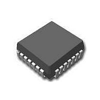
MC10H116FNG ON Semiconductor, MC10H116FNG Datasheet - Page 2

MC10H116FNG
Manufacturer Part Number
MC10H116FNG
Description
IC LINE RCVR TRIPLE ECL 20PLCC
Manufacturer
ON Semiconductor
Series
10Hr
Datasheet
1.MC10H116MEL.pdf
(6 pages)
Specifications of MC10H116FNG
Number Of Drivers/receivers
*
Protocol
*
Mounting Type
Surface Mount
Package / Case
20-PLCC
Operating Temperature
0°C ~ 75°C
Logic Type
Line Receiver
Number Of Bits
*
Logic Family
10H
Supply Voltage (max)
- 5.46 V
Supply Voltage (min)
- 4.94 V
Maximum Operating Temperature
75 C
Mounting Style
SMD/SMT
Maximum Power Dissipation
85 mW
Minimum Operating Temperature
0 C
Number Of Lines (input / Output)
/ /
Supply Current
21 mA
Msl
MSL 3 - 168 Hours
Supply Voltage Range
-4.94V To -5.46V
Filter Terminals
SMD
Driver Case Style
LCC
No. Of Pins
20
Rohs Compliant
Yes
Family Type
ECL
Input Type
ECL/HSTL
Leaded Process Compatible
Yes
Logic Base Number
H116
Logic Case Style
LCC
Lead Free Status / RoHS Status
Lead free / RoHS Compliant
Supply Voltage
-
Lead Free Status / Rohs Status
Lead free / RoHS Compliant
Available stocks
Company
Part Number
Manufacturer
Quantity
Price
Company:
Part Number:
MC10H116FNG
Manufacturer:
ON Semiconductor
Quantity:
135
Company:
Part Number:
MC10H116FNG
Manufacturer:
ON Semiconductor
Quantity:
10 000
Part Number:
MC10H116FNG
Manufacturer:
ON/安森美
Quantity:
20 000
Maximum ratings are those values beyond which device damage can occur. Maximum ratings applied to the device are individual stress limit
values (not normal operating conditions) and are not valid simultaneously. If these limits are exceeded, device functional operation is not implied,
damage may occur and reliability may be affected.
1. When V
2. Each MECL 10H™ series circuit has been designed to meet the specifications shown in the test table, after thermal equilibrium has been
3. Differential input not to exceed 1.0 Vdc.
4. 150 mV
NOTE: Device will meet the specifications after thermal equilibrium has been established when mounted in a test socket or printed circuit
Table 1. MAXIMUM RATINGS
Symbol
Table 2. ELECTRICAL CHARACTERISTICS
Symbol
Table 3. AC CHARACTERISTICS
Symbol
V
V
I
T
T
I
I
I
V
V
V
V
V
V
V
t
t
t
out
E
inH
CBO
pd
r
f
A
stg
EE
I
BB
OH
OL
IH
IL
CMR
PP
established. The circuit is in a test socket or mounted on a printed circuit board and transverse air flow greater than 500 linear fpm is
maintained. Outputs are terminated through a 50−ohm resistor to −2.0 V.
board with maintained transverse airflow greater than 500 lfpm. Electrical parameters are guaranteed only over the declared
operating temperature range. Functional operation of the device exceeding these conditions is not implied. Device specification limit
values are applied individually under normal operating conditions and not valid simultaneously.
p−p
BB
Power Supply (V
Input Voltage (V
Output Current
Operating Temperature Range
Storage Temperature Range − Plastic
Power Supply Current
Input Current High
Input Leakage Current
Reference Voltage
High Output Voltage
Low Output Voltage
High Input Voltage (Note 1)
Low Input Voltage (Note 1)
Common Mode
Input Sensitivity (Note 3)
Propagation Delay
Rise Time
Fall Time
is used as the reference voltage.
differential input required to obtain full logic swing on output.
CC
CC
Characteristic
= 0)
Characteristic
= 0)
− Continuous
− Surge
Range (Note 4)
− Ceramic
Characteristic
(V
EE
= −5.2 V ±5%) (Note 2)
http://onsemi.com
−1.38
−1.02
−1.95
−1.17
−1.95
Min
2
−
−
−
−
−
Min
0.4
0.5
0.5
0°
0°
−1.27
−0.84
−1.63
−0.84
−1.48
Max
150
1.5
23
−
−
Max
1.3
1.5
1.5
−1.35
−0.98
−1.95
−1.13
−1.95
Min
−2.85 to −0.8
−
−
−
Min
0.4
0.5
0.5
150 typ
25°
25°
−1.25
−0.81
−1.63
−0.81
−1.48
Max
1.0
21
95
Max
1.3
1.6
1.6
−55 to +150
−55 to +165
−8.0 to 0
0 to V
0 to +75
Rating
100
−1.31
−0.92
−1.95
−1.07
−1.95
50
Min
0.45
Min
0.5
0.5
−
−
−
−
−
EE
75°
75°
−0.735
−0.735
−1.19
−1.60
−1.45
Max
Max
1.45
1.0
23
95
1.7
1.7
−
−
mV
Unit
Unit
Unit
Vdc
Vdc
Vdc
Vdc
Vdc
Vdc
Vdc
Vdc
mA
mA
°C
°C
°C
mA
mA
ns
ns
ns
PP


