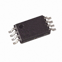
AT24C128B-TH-B Atmel, AT24C128B-TH-B Datasheet - Page 6

AT24C128B-TH-B
Manufacturer Part Number
AT24C128B-TH-B
Description
IC EEPROM 128KBIT 1MHZ 8TSSOP
Manufacturer
Atmel
Datasheet
1.AT24C128BN-SH-B.pdf
(23 pages)
Specifications of AT24C128B-TH-B
Format - Memory
EEPROMs - Serial
Memory Type
EEPROM
Memory Size
128K (16K x 8)
Speed
400kHz, 1MHz
Interface
I²C, 2-Wire Serial
Voltage - Supply
1.8 V ~ 5.5 V
Operating Temperature
-40°C ~ 85°C
Package / Case
8-TSSOP
Organization
16 K x 8
Interface Type
2-Wire
Maximum Clock Frequency
1 MHz
Access Time
900 ns
Supply Voltage (max)
5.5 V
Supply Voltage (min)
1.8 V
Maximum Operating Current
3 mA
Maximum Operating Temperature
+ 85 C
Mounting Style
SMD/SMT
Minimum Operating Temperature
- 40 C
Operating Supply Voltage
2.5 V, 3.3 V
Lead Free Status / RoHS Status
Lead free / RoHS Compliant
Available stocks
Company
Part Number
Manufacturer
Quantity
Price
Company:
Part Number:
AT24C128B-TH-B
Manufacturer:
Atmel
Quantity:
15
Company:
Part Number:
AT24C128B-TH-B
Manufacturer:
ATMEL10
Quantity:
120
Part Number:
AT24C128B-TH-B
Manufacturer:
ATMEL/爱特梅尔
Quantity:
20 000
6. Device Operation
6
AT24C128B
CLOCK and DATA TRANSITIONS: The SDA pin is normally pulled high with an external device.
Data on the SDA pin may change only during SCL low time periods (see
changes during SCL high periods will indicate a start or stop condition as defined below.
Figure 6-1.
START CONDITION: A high-to-low transition of SDA with SCL high is a start condition that must
precede any other command (see
Figure 6-2.
STOP CONDITION: A low-to-high transition of SDA with SCL high is a stop condition. After a
read sequence, the stop command will place the EEPROM in a standby power mode (see
ure
ACKNOWLEDGE: All addresses and data words are serially transmitted to and from the
EEPROM in 8-bit words. The EEPROM sends a “0” during the ninth clock cycle to acknowledge
that it has received each word.
STANDBY MODE: The AT24C128B features a low-power standby mode that is enabled upon
power-up and after the receipt of the stop bit and the completion of any internal operations.
SOFTWARE RESET: After an interruption in protocol, power loss or system reset, any 2-wire
part can be protocol reset by following these steps: (a) Create a start bit condition, (b) clock 9
6-2).
SDA
SCL
SDA
SCL
Data Validity
Start and Stop Definition
START
DATA STABLE
Figure
6-2).
CHANGE
DATA
DATA STABLE
STOP
Figure
5296A–SEEPR–1/08
6-1). Data
Fig-


