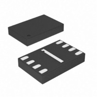
M95320-RMB6TG STMicroelectronics, M95320-RMB6TG Datasheet - Page 31

M95320-RMB6TG
Manufacturer Part Number
M95320-RMB6TG
Description
IC EEPROM 32KBIT 5MHZ 8MLP
Manufacturer
STMicroelectronics
Datasheet
1.M95320-WMN6TP.pdf
(44 pages)
Specifications of M95320-RMB6TG
Format - Memory
EEPROMs - Serial
Memory Type
EEPROM
Memory Size
32K (4K x 8)
Speed
5MHz
Interface
SPI, 3-Wire Serial
Voltage - Supply
1.8 V ~ 5.5 V
Operating Temperature
-40°C ~ 85°C
Package / Case
8-MLP, 8-UFDFPN
Organization
4 K x 8
Interface Type
SPI
Maximum Clock Frequency
5 MHz
Access Time
80 ns
Supply Voltage (max)
5.5 V
Supply Voltage (min)
1.8 V
Maximum Operating Current
3 mA
Maximum Operating Temperature
+ 85 C
Mounting Style
SMD/SMT
Minimum Operating Temperature
- 40 C
Operating Supply Voltage
2.5 V, 3.3 V, 5 V
Memory Configuration
4096 X 8
Clock Frequency
5MHz
Supply Voltage Range
1.8V To 5.5V
Memory Case Style
DFN
No. Of Pins
8
Rohs Compliant
Yes
Lead Free Status / RoHS Status
Lead free / RoHS Compliant
Other names
497-8713-2
M95320-RMB6TG
M95320-RMB6TG
Available stocks
Company
Part Number
Manufacturer
Quantity
Price
Part Number:
M95320-RMB6TG
Manufacturer:
ST
Quantity:
20 000
M95320, M95320-W, M95320-R
Table 18.
1. t
2. Value guaranteed by characterization, not 100% tested in production.
3. t
Symbol
t
t
t
t
t
t
t
CLCH
CHCL
SHQZ
CLQV
QLQH
QHQL
HLQZ
t
t
t
t
t
t
t
t
t
t
t
t
t
t
t
ns, t
t
SHCH
CHSH
DVCH
CHDX
HHCH
HHQV
SLCH
SHSL
CHSL
CH
HLCH
CLHH
CLQX
CH
CLQV
CLQV
CL
CLHL
t
f
W
C
(1)
(1)
+ t
CL
(2)
(2)
(2)
(2)
(3)
(2)
(2)
+t
must be compatible with t
CL
can be equal to (or greater than) t
SU
must never be lower than the shortest possible clock period, 1/f
.
t
t
AC characteristics (M95320-W, device grade 6)
f
t
t
t
CSS1
CSS2
t
Alt.
t
t
CSH
t
DSU
t
t
t
SCK
t
CLH
t
t
t
CLL
t
DIS
WC
CS
RC
DH
HO
RO
FO
FC
t
HZ
LZ
V
Clock frequency
S active setup time
S not active setup time
S deselect time
S active hold time
S not active hold time
Clock high time
Clock low time
Clock rise time
Clock fall time
Data in setup time
Data in hold time
Clock low hold time after HOLD not active
Clock low hold time after HOLD active
Clock low set-up time before HOLD active
Clock low set-up time before HOLD not active
Output disable time
Clock low to output valid
Output hold time
Output rise time
Output fall time
HOLD high to output valid
HOLD low to output high-Z
Write time
Test conditions specified in
CL
Doc ID 5711 Rev 12
(clock low time): if the SPI bus master offers a Read setup time t
CLQV
Parameter
; in all other cases, t
Table 9
CL
and
must be equal to (or greater than)
Table 11
C
(max).
DC and AC parameters
Min.
D.C.
30
30
40
30
30
42
40
10
10
30
30
0
0
0
Max.
10
40
40
40
40
40
40
2
2
5
SU
= 0
MHz
Unit
ms
ns
ns
ns
ns
ns
ns
ns
µs
µs
ns
ns
ns
ns
ns
ns
ns
ns
ns
ns
ns
ns
ns
31/44


