DS1245YP-70+ Maxim Integrated Products, DS1245YP-70+ Datasheet
DS1245YP-70+
Specifications of DS1245YP-70+


Related parts for DS1245YP-70+


DS1245YP-70+ Summary of contents
Page 1
... Data is automatically protected during power loss Replaces 128k x 8 volatile static RAM, EEPROM or Flash memory Unlimited write cycles Low-power CMOS Read and write access times Lithium energy source is electrically ...
Page 2
DESCRIPTION The DS1245 1024k Nonvolatile SRAMs are1,048,576-bit, fully static, nonvolatile SRAMs organized as 131,072 words by 8 bits. Each complete NV SRAM has a self-contained lithium energy source and control circuitry which constantly monitors V occurs, the lithium energy source ...
Page 3
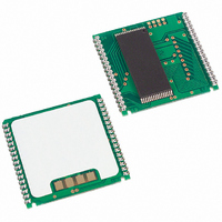
... PACKAGES The DS1245 devices are available in two packages: 32-pin DIP and 34-pin PowerCap Module (PCM). The 32-pin DIP integrates a lithium battery, an SRAM memory and a nonvolatile control function into a single package with a JEDEC-standard 600-mil DIP pinout. The 34-pin PowerCap Module integrates SRAM memory and nonvolatile control along with contacts for connection to the lithium battery in the DS9034PC PowerCap ...
Page 4
ABSOLUTE MAXIMUM RATINGS Voltage on Any Pin Relative to Ground Operating Temperature Range Commercial: Industrial: Storage Temperature Range EDIP PowerCap Lead Temperature (soldering, 10s) Soldering Temperature (reflow, PowerCap) Note: EDIP is wave or hand soldered only. This is a stress ...
Page 5
AC ELECTRICAL CHARACTERISTICS PARAMETER Read Cycle Time Access Time to Output Valid OE to Output Valid Output Active OE CE Output High Z from Deselection Output Hold from Address Change Write Cycle Time Write Pulse Width Address ...
Page 6
READ CYCLE SEE NOTE 1 WRITE CYCLE 1 SEE NOTES and DS1245Y/AB ...
Page 7
WRITE CYCLE 2 SEE NOTES and 13 POWER-DOWN/POWER-UP CONDITION DS1245Y/AB ...
Page 8
POWER-DOWN/POWER-UP TIMING PARAMETER V Fail Detect to and slew from slew from Valid to and Inactive Valid to End of ...
Page 9
... DS1245ABP-70+ 0°C to +70°C DS1245AB-70IND+ -40°C to +85°C DS1245ABP-70IND+ -40°C to +85°C DS1245Y-70+ 0°C to +70°C DS1245YP-70+ 0°C to +70°C DS1245Y-70IND+ -40°C to +85°C DS1245YP-70IND+ -40°C to +85°C +Denotes a lead(Pb)-free/RoHS-compliant package. *DS9034PC+ or DS9034PCI+ (PowerCap) required. Must be ordered separately. PACKAGE INFORMATION For the latest package outline information and land patterns www.maxim-ic.com/packages. “ ...
Page 10
REVISION HISTORY REVISION DATE Added Package Information table; removed the DIP module package 121907 drawing and dimension table Updated the storage information, soldering temperature, and lead temperature information in the Absolute Maximum Ratings section; removed the -85, -100, and -120 ...